Smart Thermostat RDS120-B Technical Instructions Advanced cloud connected thermostat for light commercial and residential applications • • • • • • • • • A6V11727385 06/20/2019 BACnet over IP Certified Controls conventional HVAC systems up to 3H/2C and heat pumps up to 4H/2C Easy to read, backlit, auto-dimming 3.
Thermostat Highlights ● ● ● ● ● ● ● ● ● ● ● ● ● ● ● Built-in VOC sensor senses wide range of offending organic odors that contribute to stale air and drives ventilation control Easy to understand tri-level air quality indication: “Good”, “Okay”, “Poor” Built-in temperature and humidity sensors Inputs for remote or averaging temperature and humidity sensors One-touch operation for “Away”, “OFF”, “FAN” and “Heating/Cooling” Configurable setpoint limits Password protected screen lock Presence detection usin
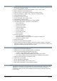
Mechanical Design The room thermostat consists of the following parts: ● Front housing with touch screen and sensors ● Back housing with terminals and relays ● Mounting hardware for installation on 2’’×4’’ electrical box or directly on drywall Operation and Settings Active Display Siemens Industry, Inc. Smart Infrastructure 1 System setup screens and detailed information display 2 Shows if the system is working in an energy-optimized mode. If the leaf is red, some predefined settings have been changed.
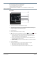
Idle Display 1 Relative humidity 2 Shows room air quality: ● Green = Very Good ● Orange = Fair ● Red = Poor 3 Shows if the system is working in an energy-optimized mode. If the leaf is red, some pre-defined settings have been changed. One touch to the leaf returns settings to configured settings and reverts leaf color to green. 4 Room temperature NOTE: Idle mode display will vary based on system configuration.
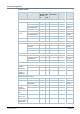
Associated Equipment Remote sensors Sensor Type Model Number 1k Ohm at 32°F Ni R 1k Type 2 Ohm Thermistor Pt RTD 0-10 Vdc Datasheet* Room Temperature Sensors - Wall-mount QAA2220.EWSN x QAA2212.EWSN 149-714 x QAA2230.EWSN 149-714 x QAA22SS.EWSN - Flushmount1) 149-714 x 149-714 540-984 (Metal) x 149-956 536-994A (Beige) x 149-956 536-994B (White) x 149-956 x 149-915 - Duct-mount QAM2030.
* The documents can be downloaded from Siemens US Download Center by specifying the product number as shown in the above table. 1) With digital display Replacement Part Description Model Number Orderable Part Number Plastic trim plate and metal mounting plate for 2’’ × 4’’ box (1 set) ARG100.
Installation Location ● ● ● ● ● ● The devices are suitable for wall installation. Recommended height: 5 feet above the floor. Do not install the devices in recesses, shelves, behind curtains or doors, or above or near heat sources. Avoid direct exposure to sun and drafts. Seal the conduit or backwall as drafts can affect sensor readings. Observe maximum ambient conditions. Wiring Use only class 2 rated power source with proper current limiting.
OS OS version App Store iOS iOS 10 or above App store® Android AndroidTM 5.0 or above Google PlayTM Maintenance The thermostat is designed for maintenance-free operation. Disposal The device is considered an electronic device for disposal in accordance with the European Guidelines and may not be disposed of as domestic garbage. ● Dispose of the device through channels provided for this purpose. ● Comply with all local and currently applicable laws and regulations.
FCC Regulations (USA) WARNING Modification of this device to receive cellular radio telephone service signals is prohibited under FCC rules and federal law. This equipment has been tested and found to comply with the limits for a Class B digital device, pursuant to part 15 of the FCC Rules. These limits are designed to provide reasonable protection against harmful interference in a residential installation.
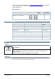
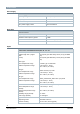
Technical data Power Supply Power Supply Operating voltage 24 Vac (±20%) Frequency 48 to 63 Hz Power consumption Max. 9 VA Max. power supply current 4 A current limited Radio Data Radio Parameter Frequency band 2.4 to 2.4835 GHz Maximum radio-frequency power 18 dBm WLAN standard IEEE 802.11b/g/n (HT20) WLAN channel 1-11 Inputs Connections to Multifunctional Inputs X1 - M - X2 Passive temperature sensors - Cable length max.
Connections to Multifunctional Inputs X1 - M - X2 - Parallel connection Max. 20 thermostats per switch - Input function Selectable Outputs Relay Contact Capacity Voltage 24 Vac (±20%) Current Min. 0.02 A, Max. 1A per output Operational Data Setpoint Range 45 to 95°F (7…35°C) Built-in Room Temperature Sensor Temperature range Accuracy at 77°F (25°C) Display resolution 32 to 122°F ±0.9 °F or 0.5°C 1 °F (0.
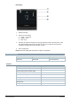
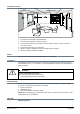
PIR Sensor Sensor Detection Range A: The width of each cell, 80 cm (31 in). B: The thermostat. C: The height of each cell, 80 cm (31 in). D: The area that the PIR sensor can detect.
Standards, Directives and Approvals FCC standards FCC CFR 47 Part 15 Subpart C IC standards RSS-247 issue 1 May 2015, RSS-GEN issue 4 November 2014 UL UL916 BTL BACnet Testing Laboratory Environmental compatibility The product environmental declaration A5W90003412*) contains data on environmentally compatible product design and assessments (RoHS compliance, materials composition, packaging, environmental benefit, disposal). *) The documents can be downloaded from http://siemens.com/bt/download.
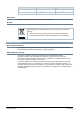
Wiring Diagrams Jumper in Place Jumper Removed NOTE: ● For US installations use Class 2 rated power source. For other installations, use current protection with current rated at max. 4A. ● If a single transformer is used, keep jumper RH-RC in place. Connect 24 Vac to the RC terminal, and neutral to terminal C. If separate transformers are used for heating and cooling systems, remove jumper RH-RC. Connect cooling 24 Vac to terminal RC, neutral to terminal C and heating 24 Vac to terminal RH.
Dimensions Siemens Industry, Inc.
Issued by Siemens Industry, Inc. Smart Infrastructure 1000 Deerfield Pkwy Buffalo Grove IL 60089 Tel. +1 847-215-1000 16 Siemens Industry, Inc. Smart Infrastructure Document ID A6V11727385 Edition 06/20/2019 © Siemens Industry, Inc., 2019 Technical specifications and availability subject to change without notice.