s Semi-flush-mounted room temperature controllers for VAV / CAV applications, with LCD RDU340 Basic Documentation Edition: 1.
/ 30 Siemens Building Technologies Basic Documentation CE1P3078.
Table of contents 1 About this document ..............................................................................4 1.1 Revision history.........................................................................................4 1.2 Reference documents ...............................................................................4 1.3 1.3.1 1.3.2 Before you start.........................................................................................4 Copyright.....................................
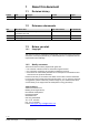
1 About this document 1.1 Revision history Edition Date Changes 1.0 11 July 2008 First edition 1.2 Section Pages Reference documents Ref. Document titel Type of document Document No. N3078 Datasheet CE1N3078en B3076 Semi-flush-mounted room temperature controllers with LCD Operating Instructions M3078 Mounting Instructions CE1B3076en CE1M3078xx 1.3 Before you start 1.3.
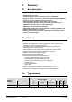
2 Summary 2.1 Brief description The devices support VAV heating and cooling systems: • • • • • • • • • • • • Modulating PI / P control Control depending on the room or the return air temperature Output for a DC 0…10 V actuator and AC 230V electrical heater (ON-OFF) Automatic or manual heating/cooling changeover Operating modes: Comfort, Energy Saving and Protection Two multifunctional inputs for keycard contact, external sensor, etc.
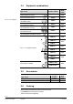
2.4 Equipment combinations Product number Data sheet Cable temperature sensor QAH11.1 1840 Room temperature sensor QAA32 1747 SSA61... 4893 SSP61… 4864 SSB61... 4891 SQS65… 4573 STS61 4880 GQD161… 4605 Type of unit DC 0..10 V actuators Electrical actuator, DC 0..10V (for radiator valve) Electrical actuator, DC 0..10V (for small valve 2,5 mm) Electrical actuator, DC 0..10V (for small valves 5.5 mm) Electromotoric actuator, DC 0..10V (for valves 5.5 mm) Thermal actuator, DC 0..
3 Use Control of the room temperature in individual rooms of ventilation or air conditioning plants that are: • Heated or cooled by single duct. • Heated and cooled by single duct with auxiliary electrical heater. The RDU340 is suitable for use with VAV systems in connection with the VAV compact controllers types G…B181.1E/3.
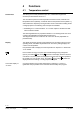
General note 4 Functions 4.1 Temperature control The setting of he control parameters (P01 etc., mentioned throughout the document) is described in section 4.11. The controller acquires the room temperature via built-in sensor, external room temperature sensor (QAA32), or external return air temperature sensor (QAH11.1), and maintains the setpoint by issuing actuator control commands to heating and/or cooling equipment. The following control outputs are available: • Modulating PI / P control with DC 0.
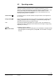
4.2 Operating modes Select the controller's operating mode via operating mode button on the controller or operating mode input (e.g. keycard occupancy sensor, when X1 or X2 set to 3 (P38, P40)). A corresponding setpoint is used to maintain the room temperature at the desired level depending on the active operating mode. The following operating modes are available: Comfort mode In Comfort mode, the controller maintains the setpoint which can be adjusted via the +/- buttons.
4.3 Setpoints Comfort mode The setpoint in Comfort mode can be adjusted via the +/- buttons. Setpoint limitation For energy saving purposes, the setpoint adjusting range can be limited to minimum (P09) and maximum (P10). P09 < P10 • If the minimum limit P09 is set lower than the maximum limit P10, both heating and cooling are adjustable between these two limits. P09 ≥ P10 • For heating or cooling applications (e.g.
4.4 Applications The controller supports following applications, which can be configured by DIPswitches on the inner side of the controller front panel.
4.5 Automatic H/C changeover Additional features The air or water temperature acquired by the changeover sensor (QAH11.1) is used to change over from heating to cooling mode and vice-versa. When the water temperature is above 28 °C (parameter P37), the controller changes over to heating mode, and to cooling mode when below 16 °C (parameter P36). If the water temperature is between the 2 changeover points immediately after power up, the controller starts in heating mode.
Min / Max air flow The output signal of the air flow (DC 0..10V) can be limited to a minimum value by using parameter P63 and to a maximum value using parameter P64. These air flow limitation values can be set between 0% and 100%. This is used to ensure a minimum or maximum supply air volume.
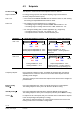
Single duct, heating or cooling In single duct applications, the controller controls an actuator (valve, damper, VAV system, etc) – in heating/cooling mode with changeover (automatic or manual), – heating only mode, – or cooling only mode. Cooling only is factory set (P01=1). The output can be limited to a minimum and maximum value if required. See section 4.5 "additional features". The diagram below shows the control sequence for continuous PI control.
4.6.2 Single duct with electrical heater If the selected application is "single duct & el. heater", then the controller works in heating and cooling mode. The output can be limited to a minimum and maximum value if required. See section 4.5 "additional features". Single duct with el. heater In single duct applications with electrical heater, the controller controls an actuator (valve, damper, VAV system, etc.) plus an auxiliary electrical heater.
4.7 Overview of control output Control output Different control output signals are available depending on the controller type. Control output on/off 3-position DC 0…10 V Type reference RDU340 Y21 (1) -- Y10 (1) ( ) Number of outputs DC 0..10 V control signal The demand calculated by the PI control from the current room temperature and setpoint is provided to the valve actuator as a continuous DC 0...10 V signal via output Y10.
4.8 Multifunctional input The controller offers two multifunctional inputs X1 and X2. A sensor of type NTC like QAH11.1 (AI) or a switch (DI) can be connected to the input terminals. The functionality of both inputs can be configured via parameters P38 for input X1 and P40 for input X2. # 0 1 Function of input X1/X2 Not used External/Return air temp. 2 Heat/cool changeover 3 Operating mode switchover 4 Dewpoint monitor 5 Enable electrical heater 6 Alarm Description No function.
4.9 Temperature out of range Error handling When the room temperature is outside the measuring range, i.e. above 49 °C or below 0 °C, the limiting temperatures flash, e.g. “0 °C” or “49 °C”. If the temperature is below 0 °C and the controller is in heating mode and the current setpoint is not set to “OFF”, then the control output Y10 or Y21 respectively will issue actuator control commands to heating equipment. For all other cases, the control output is de-energized.
4.11 Control parameters A number of control parameters can be readjusted to optimize control performance. These parameters can also be set during operation without opening the unit. In the event of a power failure, all control parameter settings are retained. The control parameters are divided in two levels: • “Service” level, and • “Expert” level. The “Service” level contains a small set of parameters to set up the controller for the HVAC system and to adjust the user interface.
# Factory setting Parameter Service Level P01 Control sequence (for application "single duct" only) 1 (Cooling only) P02 Mode selection via user operating mode button 1 (Stb, Comf) P04 Selection of °C or °F °C Setting range 0:= Heating only 1:= Cooling only 2:= Manual H/C 3:= Auto changeover 1 = Stb,Comf 2 = Stb, Comf, Eco (0) °C (1) °F – 3 ... +3 K P05 Sensor calibration 0.
Factory setting Parameter Expert Level P30 P-band/switching differential for heating mode P31 P-band/switching differential for cooling mode P33 Dead zone in Comfort mode P35 Integral time P36 Heating/cooling changeover switching point for cooling P37 Heating/cooling changeover switching point for heating P38 X1 functionality 2K 1K 2K 5 min 16 °C 28 °C 3 (Op mode switchover) P39 Operating action for X1 if digital input 0 (N.O.
5 Handling 5.1 Mounting and installation Mount the room controller on a recessed rectangular conduit box with 60.3mm fixing centers. Do not mount on a wall in niches or bookshelves, behind curtains, above or near heat sources, or exposed to direct solar radiation. Mount about 1.5 m above the floor. Mounting • Devices must be mounted on clean, dry indoor place and not be exposed to dripping or splashing Wiring See the mounting instructions M3076 enclosed with the controller.
5.2 Operating Instructions See the operating instructions B3076 enclosed with the controller. 5.3 Disposal The device is classified as waste electronic equipment in terms of the European Directive 2002/96/EC (WEEE) and should not be disposed of as unsorted municipal waste. The relevant national legal rules are to be adhered to. Regarding disposal, use the systems setup for collecting electronic waste. Observe all local and applicable laws.
6 Engineering 6.1 Connection terminals G X1 M X2 SELV L Y21 G0 Y10 G0 G, G0 L 230 V Y21 Y10 X1, X2 M 6.2 Application: Operating voltage controller AC 24 V Operating voltage for electrical heater AC Control output for electrical heater Control output for DC 0…10 V actuator Multifunctional input for temperature sensor (e.g. QAH11.1) or switch Measuring neutral for sensor and switch Connection diagrams G Single duct B2 S1 AC 24V N1 Y1 S1 QAH11.1 + ARG86.
7 Mechanical design The controller consists of 2 parts: • Front panel accommodating the electronics, operating elements and built-in room temperature sensor. • Mounting base with the power electronics. The rear of the mounting base contains the screw terminals. The base fits on a rectangular conduit box with 60.3 mm fixing centers. Slide the front panel in the mounting base and snap on. Operation and settings 1 1. Operating mode selector/Standby 2. Adjust setpoint and control parameters 2.
7.
8 Power supply Outputs Inputs Technical data Operating voltage Frequency Power consumption Control output Y10-G0 Resolution Current Control output Y21-L (N.O.
Environmental conditions Standards Operation Climatic conditions Temperature Humidity Transport Climatic conditions Temperature Humidity Mechanical conditions Storage Climatic conditions Temperature Humidity conformity EMC directive Low-voltage directive As per IEC 721-3-3 Class 3K5 0 ...+ 50 °C < 95 % r.h. As per IEC 721-3-2 Class 2K3 − 25...+60 °C < 95 % r.h. Class 2M2 As per IEC 721-3-1 Class 1K3 − 25...+60 °C < 95 % r.h.
Index A Adapter plate .......................................................... 6 Alarm .................................................................... 17 Automatic H/C changeover................................... 12 Automatic heating/cooling changeover................. 13 C Calibrate sensor.................................................... 22 Comfort mode ......................................................... 9 Commissioning .....................................................
Siemens Switzerland Ltd. Building Technologies Division International Headquarters Gubelstrasse 22 CH-6301 Zug Tel. +41 41-724 24 24 Fax +41 41-724 35 22 www.siemens.com/sbt © 2008 Siemens Switzerland Ltd.