Remote Displays SITRANS RD100 Operating Instructions 01/2011 SITRANS
Safety Guidelines: Warning notices must be observed to ensure personal safety as well as that of others, and to protect the product and the connected equipment. These warning notices are accompanied by a clarification of the level of caution to be observed. Qualified Personnel: This device/system may only be set up and operated in conjunction with this manual. Qualified personnel are only authorized to install and operate this equipment in accordance with established safety practices and standards.
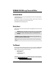
SITRANS RD100 Loop Powered Meter SITRANS RD100 SITRANS RD100 is a 2-wire loop powered, NEMA 4X enclosed remote digital display for process instrumentation. This digital meter is easy to use with a display of 3.5 digits, 1" (2.54 cm) high. It accepts 4 to 20 mA input and operates from -40 to +80 °C (-40 to +176 °F). SITRANS RD100 is CSA and FM Approved. Safety Notes Special attention must be paid to warnings and notes highlighted from the rest of the text by grey boxes.
Specifications Note: Except where noted, all specifications apply to operation at +25 °C (+77 °F). Display • 1.0 " (25.
Calibration • Two-step; non-interacting low and high Calibration Range • 4 mA input: display of -1000 to +1000 counts • 20 mA input: display of 4 mA count value +20 to 2000 counts, to a max. display of 1999 counts Accuracy • ±0.1% of span ±1 count Conversion Rate • 2.
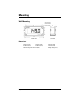
Mounting Wall Mounting D wall mounting holes beneath cover screws E F C A B SIDE VIEW FRONT VIEW Dimensions A: 80 mm (3.15") C: 60 mm (2.36") B: 140 mm (5.51") D: 120 mm (4.72") Wall mounting holes: Ø 4 mm (0.16") Page 4 E: 65 mm (2.56") F: 20 mm (0.
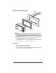
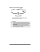
Optional Panel Mounting Kit mounting bracket self tapping screw washers panel mounting plate RD100 Notes • • The optional panel mounting kit does not provide a NEMA 4X seal to panel. Mounting brackets require 20 mm (0.8") clearance on either the top or the side of the meter for installation. • Allowable panel thickness: 1.5 mm - 3.2 mm (0.060" - 0.125") • Mounting plate dimensions: 163.3 mm x 102.9 mm x 3.2 mm (6.43" x 4.05" x 0.125") • Panel cutout required: 138.4 mm x 77.5 mm (5.45" x 3.
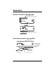
Connections Calibrator connected to input signal PCB display PCB component side (may be removed for bench calibration) LO calibration control HI calibration control balance control (factory adjust only) DP1 DP2 DP3 S+ Sblack red S+ SS- S+ loop jumper input signal PCB (mounted to base of enclosure) calibrated current source Control loop connected to input signal PCB input signal PCB S+ S- S- S+ loop jumper (remove when display PCB is connected) 4-20 mA power supply Field wiring is made to the input
Calibrator connected to display PCB display PCB component side DP1 DP2 DP3 S+ S- calibrated current source The display PCB may be removed from the enclosure for bench calibration. Loop jumper must be installed on input signal PCB to maintain loop. Refer to Servicing display PCB outside the loop on page 9. WARNINGS: • To maintain hazardous area protection, the input signal must always be connected to the input signal PCB, and not directly to the display PCB. • Electrostatic hazard.
Setup WARNINGS: • If any of the following operations are performed in the hazardous area, all appropriate hazardous area procedures must be followed. • To prevent damage to electronic components caused by electrostatic discharge, a grounding strap should be worn when servicing the display. For calibration, a calibrated current source and a screwdriver are required. Calibration connections To access the input terminals, remove the enclosure cover and the display PCB. 1. 2. 3. 4.
further details. Wall mounting holes are located in each corner of the enclosure (see Mounting on page 4). Loop connections Disconnect power to the loop and install the meter as illustrated in Control loop connected to input signal PCB on page 6 and Removing display PCB from the loop on page 9. Replace the enclosure cover. Removing display PCB from the loop The display PCB and input signal PCB are connected together with one black and one red wire.
www.siemens.com/processautomation For more information www.siemens.com/level www.siemens.com/weighing Siemens AG Industry Sector 1954 Technology Drive P.O. Box 4225 Peterborough, ON Canada K9J 7B1 Subject to change without prior notice 7ML19985JU01 Rev. 1.1 © Siemens AG 2011 email: techpubs.smpi@siemens.com www.siemens.