
System Manual Part 1
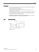
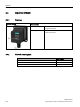
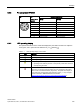
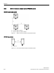
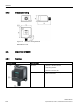

Table Of Contents
- SIMATIC RF200
- Table of contents
- 1 Introduction
- 2 Safety notes
- 3 System overview
- 4 Planning the RF200 system
- 4.1 Fundamentals of application planning
- 4.1.1 Selection criteria for SIMATIC RF200 components
- 4.1.2 Transmission window and read/write distance
- 4.1.3 Width of the transmission window
- 4.1.4 Impact of secondary fields
- 4.1.5 Permissible directions of motion of the transponder
- 4.1.6 Operation in static and dynamic mode
- 4.1.7 Dwell time of the transponder
- 4.1.8 Communication between communication module, reader and transponder
- 4.2 Field data of transponders and readers
- 4.3 Installation guidelines
- 4.4 Further information
- 4.1 Fundamentals of application planning
- 5 Readers
- 5.1 SIMATIC RF210R
- 5.2 SIMATIC RF210M
- 5.3 SIMATIC RF220R
- 5.4 SIMATIC RF240R
- 5.5 SIMATIC RF250R
- 5.6 SIMATIC RF260R
- 5.7 SIMATIC RF280R
- 5.8 SIMATIC RF290R
- 6 Antennas

Readers
5.5 SIMATIC RF250R
SIMATIC RF200
System Manual, 07/2017, J31069-D0227-U001-A9-7619
129
Note
Reader requires external antennas
Note that the RF250R reader is designed only for operation with external antennas and can
only be operated in conjunction with the antennas ANT 3, ANT 8, ANT 12, ANT 18 o
r ANT
30.
5.5.2
Ordering data RF250R
Article number
RF250R with RS-422 interface (3964R)
6GT2821-5AC10
RF250R with RS-232 interface (ASCII)
6GT2821-5AC40
5.5.3
Pin assignment RF250R
Pin
Pin
Device end 8-
pin M12
Interface assignment
RS-422
RS-232
1
+24 V
+24 V
2
- Transmit
RXD
3
0 V
0 V
4
+ Transmit
TXD
5
+ Receive
Unassigned
6
- Receive
Unassigned
7
Unassigned
Unassigned
8
Ground (shield)
Ground (shield)
5.5.4
LED operating display
The operational statuses of the reader are displayed by the LEDs. The LED can adopt the
colors green, red or yellow and the statuses off
, on , flashing :
Table 5- 9 LED operating display on the reader
LED
Meaning
The reader is turned off.
Operating voltage present, reader not initialized or antenna switched off
Operating voltage present, reader initialized and antenna switched on