
System Manual Part 1
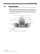
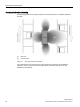

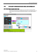
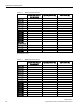
Table Of Contents
- SIMATIC RF200
- Table of contents
- 1 Introduction
- 2 Safety notes
- 3 System overview
- 4 Planning the RF200 system
- 4.1 Fundamentals of application planning
- 4.1.1 Selection criteria for SIMATIC RF200 components
- 4.1.2 Transmission window and read/write distance
- 4.1.3 Width of the transmission window
- 4.1.4 Impact of secondary fields
- 4.1.5 Permissible directions of motion of the transponder
- 4.1.6 Operation in static and dynamic mode
- 4.1.7 Dwell time of the transponder
- 4.1.8 Communication between communication module, reader and transponder
- 4.2 Field data of transponders and readers
- 4.3 Installation guidelines
- 4.4 Further information
- 4.1 Fundamentals of application planning
- 5 Readers
- 5.1 SIMATIC RF210R
- 5.2 SIMATIC RF210M
- 5.3 SIMATIC RF220R
- 5.4 SIMATIC RF240R
- 5.5 SIMATIC RF250R
- 5.6 SIMATIC RF260R
- 5.7 SIMATIC RF280R
- 5.8 SIMATIC RF290R
- 6 Antennas

Planning the RF200 system
4.1 Fundamentals of application planning
SIMATIC RF200
System Manual, 07/2017, J31069-D0227-U001-A9-7619
31
4.1.4
Impact of secondary fields
Secondary fields in the range from 0 mm to 30% of the limit distance (S
g
) generally always
exist.
They should, however, only be used during configuration in exceptional cases, since the
read/write distances are very limited. Exact details of the secondary field geometry cannot be
given, since these values depend heavily on the operating distance and the application.
When working in dynamic mode, remember that during the transition from the secondary
field to the main field the presence of the tag is lost temporarily. It is therefore advisable to
select a distance > 30 % of S
g
.
①
Main field
②
Secondary field
Figure 4-3 Gap in the field resulting from secondary fields