
System Manual Part 1
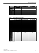
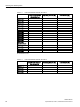
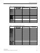
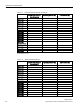
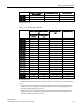
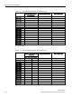
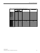
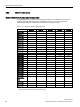
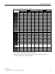
Table Of Contents
- SIMATIC RF200
- Table of contents
- 1 Introduction
- 2 Safety notes
- 3 System overview
- 4 Planning the RF200 system
- 4.1 Fundamentals of application planning
- 4.1.1 Selection criteria for SIMATIC RF200 components
- 4.1.2 Transmission window and read/write distance
- 4.1.3 Width of the transmission window
- 4.1.4 Impact of secondary fields
- 4.1.5 Permissible directions of motion of the transponder
- 4.1.6 Operation in static and dynamic mode
- 4.1.7 Dwell time of the transponder
- 4.1.8 Communication between communication module, reader and transponder
- 4.2 Field data of transponders and readers
- 4.3 Installation guidelines
- 4.4 Further information
- 4.1 Fundamentals of application planning
- 5 Readers
- 5.1 SIMATIC RF210R
- 5.2 SIMATIC RF210M
- 5.3 SIMATIC RF220R
- 5.4 SIMATIC RF240R
- 5.5 SIMATIC RF250R
- 5.6 SIMATIC RF260R
- 5.7 SIMATIC RF280R
- 5.8 SIMATIC RF290R
- 6 Antennas

Planning the RF200 system
4.3 Installation guidelines
SIMATIC RF200
50 System Manual, 07/2017, J31069-D0227-U001-A9-7619
Minimum distance from reader to reader
Table 4- 17 Minimum distances to readers or antennas
RF210R to
RF210R
RF220R to
RF220R
RF240R to
RF240R
ANT x to ANT x
with RF250R
RF260R to
RF260R
RF280R to
RF280R
ANT Dx to ANT
Dx
with RF290R
≥ 60 ≥ 100 ≥ 120
ANT 3: ≥ 100
≥ 150 with 2
readers ≥
400
with multi-
ple read-
ers ≥ 500
ANT D5: ≥ 2000
ANT 8: ≥ 50 ANT D10: ≥
2000
ANT 12: ≥ 60
ANT 18: ≥ 80
ANT 30: ≥ 100
All values are in mm
Note
Effect on inductive fields by not maintaining the minimum distances of the readers
If the values fall below those specified in the "minimum distance readers or antennas", there
is a risk of the function being affected by inductive fields. In this case, the data transfer time
would
increase unpredictably or a command would be aborted with an error.
Keeping to the values specified in the "Minimum distance readers or antennas" table is
therefore essential.
If the specified minimum distance cannot be complied with due to the physical configuration,
the SET-ANT command can be used to activate and deactivate the HF field of the reader.
The application software must be used to ensure that only one reader is active (antenna is
switched on) at a time.
4.3
Installation guidelines
4.3.1
Overview
The transponder and reader complete with their antennas are inductive devices. Any type of
metal in the vicinity of these devices affects their functionality. Some points need to be
considered during planning and installation if the values described in the "Field data
(Page 39)" section are to retain their validity:
● Minimum spacing between two readers or their antennas
● Minimum distance between two adjacent data memories
● Metal-free area for flush-mounting of readers or their antennas and transponders in metal
● Mounting of multiple readers or their antennas on metal frames or racks