
System Manual Part 1

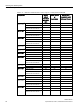
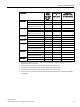

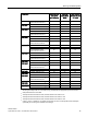

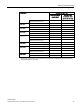
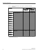


Table Of Contents
- SIMATIC RF200
- Table of contents
- 1 Introduction
- 2 Safety notes
- 3 System overview
- 4 Planning the RF200 system
- 4.1 Fundamentals of application planning
- 4.1.1 Selection criteria for SIMATIC RF200 components
- 4.1.2 Transmission window and read/write distance
- 4.1.3 Width of the transmission window
- 4.1.4 Impact of secondary fields
- 4.1.5 Permissible directions of motion of the transponder
- 4.1.6 Operation in static and dynamic mode
- 4.1.7 Dwell time of the transponder
- 4.1.8 Communication between communication module, reader and transponder
- 4.2 Field data of transponders and readers
- 4.3 Installation guidelines
- 4.4 Further information
- 4.1 Fundamentals of application planning
- 5 Readers
- 5.1 SIMATIC RF210R
- 5.2 SIMATIC RF210M
- 5.3 SIMATIC RF220R
- 5.4 SIMATIC RF240R
- 5.5 SIMATIC RF250R
- 5.6 SIMATIC RF260R
- 5.7 SIMATIC RF280R
- 5.8 SIMATIC RF290R
- 6 Antennas

Planning the RF200 system
4.3 Installation guidelines
SIMATIC RF200
System Manual, 07/2017, J31069-D0227-U001-A9-7619
75
Transponder
Reader without
metal direct
metal influence
Reader on
metal (metal
plate)
Flush-mounted
in metal (20 mm
all-round)
Flush-mounted in metal;
distance all round 20 mm
3)
65 60 55
MDS D261
Without metal 100 95 85
On metal; distance 25 mm
4)
85
80
75
MDS D324
1)
Without metal 100 95 85
On metal; distance 15 mm
85
85
80
Flush-mounted in metal;
distance all round 25 mm
2)
70 65 60
MDS D339
1)
Without metal
100
90
80
On metal; distance 30 mm
85
80
75
Flush-mounted in metal;
distance all round 100 mm
4)
80 75 70
MDS D400
1)
Without metal
100
90
80
On metal; distance 20 mm
75
70
60
Flush-mounted in metal;
distance all round 20 mm
4)
60 60 55
MDS D423
Without metal
100
95
85
On metal; distance 0 mm
100
5)
100
5)
90
5)
Flush-mounted in metal;
distance all round 10 mm
2)
75 65 60
MDS D424
1)
MDS D524
1)
Without metal
100
90
75
On metal; distance 15 mm 75 75 60
Flush-mounted in metal;
distance all round 25 mm
2)
60 55 40
MDS D425
MDS D525
Without metal
100
70
90
On metal; distance 0 mm
2)
75
70
60
MDS D426
1)
MDS D526
1)
Without metal
100
90
80
On metal; distance 25 mm
80
75
70
Flush-mounted in metal;
distance all round 50 mm
3)
75 65 65
MDS D428
MDS D528
Without metal
100
90
80
On metal; distance 0 mm
2)
85
80
65
MDS D460
1)
Without metal
100
95
80
On metal; distance 10 mm
2)
80
75
60
1)
Mounting the transponder on or in metal is only possible with the appropriate spacer or if there is
adequate clearance to the metal.
2)
Transponder flush-mounted in metal; minimum distance to reader 5 mm
3)
Transponder flush-mounted in metal; minimum distance to reader 10 mm
4)
Transponder flush-mounted in metal; minimum distance to reader 15 mm
5)
Values > 100 % in relation to non-metal surroundings can occur if transponders were developed
specifically for mounting in/on metallic surroundings.