
System Manual Part 1
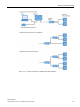
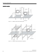
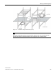

Table Of Contents
- SIMATIC RF200
- Table of contents
- 1 Introduction
- 2 Safety notes
- 3 System overview
- 4 Planning the RF200 system
- 4.1 Fundamentals of application planning
- 4.1.1 Selection criteria for SIMATIC RF200 components
- 4.1.2 Transmission window and read/write distance
- 4.1.3 Width of the transmission window
- 4.1.4 Impact of secondary fields
- 4.1.5 Permissible directions of motion of the transponder
- 4.1.6 Operation in static and dynamic mode
- 4.1.7 Dwell time of the transponder
- 4.1.8 Communication between communication module, reader and transponder
- 4.2 Field data of transponders and readers
- 4.3 Installation guidelines
- 4.4 Further information
- 4.1 Fundamentals of application planning
- 5 Readers
- 5.1 SIMATIC RF210R
- 5.2 SIMATIC RF210M
- 5.3 SIMATIC RF220R
- 5.4 SIMATIC RF240R
- 5.5 SIMATIC RF250R
- 5.6 SIMATIC RF260R
- 5.7 SIMATIC RF280R
- 5.8 SIMATIC RF290R
- 6 Antennas

Planning the RF200 system
4.3 Installation guidelines
SIMATIC RF200
System Manual, 07/2017, J31069-D0227-U001-A9-7619
87
●
The metal parts must not form closed loops or circuits. If necessary, these must be
electrically interrupted at one point
.
● The metal parts in the immediate vicinity of the antenna must be grounded in a mesh with
a good HF connection.
● Since the write/read device is installed in a metal housing, and the antennas can couple
into the cables to the write/read device, it must be installed at a distance of at least 500
mm from the antennas.
Notes on installing and laying the antenna cable
To suppress possible interference, an EMC hinged ferrite choke must be fitted to the
antenna cables (as well as the antenna cable between the reader and the antenna splitter).
The coaxial cable must be wound tightly at least four times through the EMC ring core. The
maximum distance between the connecting plug for the reader or the antenna splitter and
the ring core must be 100 mm.
The antenna cable must always be run vertically from the antennas. A minimum distance of
200 mm to the antennas must be observed as the cables continue. Otherwise, performance
losses must be expected.
There must be a distance of at least 300 mm between antenna cables and parallel power
cables.
Unrequired cable length must be secured in a bundle with a diameter of 100 to 150 mm.
If the standard antenna cable is too short, it can be increased by 7.20 m with the extension.
Slight range losses must be expected here.
To achieve optimal read ranges, the antenna cable should not be shortened or lengthened.