Antennas 6.3 ANT 8 6.3.3 Transmission window Ld Length of the transmission window (= 3 mm) Sa Operating distance between antenna and transponder Sg Limit distance (maximum clear distance between upper surface of the reader and the antenna, at which the transmission can still function under normal conditions) Figure 6-10 6.3.
Transponder 7.
System integration 8 The communication modules (interface modules) are links between the RFID components (reader and transponder) and the higher-level controllers (e.g. SIMATIC S7), or PCs or computers.
System integration Interface modules/communication modules and function blocks The following table shows the most important features of the interface modules/communication modules, as well as the compatible function blocks. When assigning parameters (HW Config) to the communications and interface modules, MOBY U, MOBY D, RF200, RF300 or RF600 must be selected.
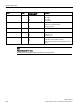
System integration ASM/ communications module S7-300 / S7-400 and STEP 7 Classic V5.5 S7-300 / S7-400 and STEP 7 Basic/Professional S7-1200 / S7-1500 and STEP 7 Basic/Professional SIMATIC RF160C FC 44 FC 44 Application blocks for RF160C Application blocks for RF160C Application blocks for RF160C FB 45 FB 45 FB 55 FB 55 FB 45 FB 45 Ident profile FB 55 FB 55 Ident blocks Standard profile V1.
System integration SIMATIC RF200 328 System Manual, 07/2017, J31069-D0227-U001-A9-7619
9 System diagnostics 9.1 Error codes of the RF200 readers Note Validity of the error codes The following error codes apply only to RF200 readers with an S-422 interface (CM mode) You can determine the error code in two ways: ● directly on the reader/CM by counting the flashing pattern of the red error LED ● via Ident profile with the "Status" output variable Give consideration to the form of the output variable in the following table ("0xE&FE$$00"; "&" = 1 ... 5; "$$" = error code).
System diagnostics 9.
System diagnostics 9.2 Diagnostics functions - STEP 7 9.2 Diagnostics functions - STEP 7 Further information on RFID diagnostics options can be found in the following function manuals: ● Function manual Ident profile and Ident blocks (https://support.industry.siemens.com/cs/us/en/view/106368029) ● Function Manual FB 45 (https://support.industry.siemens.com/cs/ww/en/view/21738808) 9.2.
System diagnostics 9.2 Diagnostics functions - STEP 7 Name Type baud byte Possible Values (hexadecimal) Transmission speed 01 03 05 multitag_SLG byte field_ON_time_SLG byte status_ant byte = 19.2 kBd = 57.6 kBd = 115.
System diagnostics 9.2 Diagnostics functions - STEP 7 9.2.2 Transponder diagnostics with "Tag Status" (MDS Status) The command can be used to scan the status data of the transponder that is located within the antenna field. Attribute "0x83" (mode 03), corresponds to UDT 230 Name Type UID array[1…8] byte MDS_type byte Possible Values (hexadecimal) Comment Unique identifier 000000000 0000000 ...
System diagnostics 9.
A Appendix A.1 Certificates & approvals All the latest RFID radio approvals are available on the Internet (http://www.siemens.com/rfid-approvals). Labeling Description Conformity acc.
Appendix A.1 Certificates & approvals Labeling Description Canadian Standard Association (CSA) acc. to standard C22.2. No. 60950 (LR 81690) or acc. to C22.2 No. 142 (LR 63533) Canadian Standard Association (CSA) per American Standard UL 60950 (LR 81690) or per UL 508 (LR 63533) This product meets the requirements of the AS/NZS 3548 Norm. USA (FCC) This device complies with Part 15 of the FCC Rules. FCC ID: NXW-RF...
Appendix A.2 Accessories A.2 Accessories A.2.1 Antenna splitter Area of application Antenna splitter Characteristics Area of application Designed for distributed mounting of antennas in warehouses, logistics and distribution Readers that can be connected RF290R Number of connectable antennas max.
Appendix A.2 Accessories Technical specifications Table A- 3 Technical specifications for antenna splitter Technical specifications max. Input power 10 W Transmission frequency 13.56 MHz Power supply None Housing dimensions (L x W x H) 160 x 80 x 40 mm (without connector) Color Anthracite Material Plastic PA 12 Connector (inputs and outputs) TNC connector Securing 2 x M5 screws Ambient temperature • During operation • -25 ℃ ... +65 ℃ • During transportation and storage • -25 ℃ ...
Appendix A.2 Accessories A.2.2 Antenna multiplexer SIMATIC RF260X A.2.2.1 Characteristics The SIMATIC RF260X antenna multiplexer can be used to operate up to six antennas on one reader.
Appendix A.2 Accessories Article number Antenna cable Antenna cable extension A.2.2.3 A.2.2.4 3.3 m 6GT2691-0CH33 10.5 m 6GT2691-0CN10 7.2 m 6GT2691-0DH72 Description ① 24 V DC power supply ② Antenna connections OUT 1 to OUT 6 with LEDs Color Status LED Yellow Lit when the corresponding antenna output is active. ③ SLG antenna connection "IN" ③ LEDs LED Color Status LED COMM / ERR Red • Flashes when the RF260X receives a signal from the SLG.
Appendix A.2 Accessories A.2.2.5 Connectors ● Power supply Pin Pin, casing side Assignment 4-pin M12 RF260X 1 Ground (0 V) 2 + 24 V 3 + 24 V 4 Ground (0 V) ● Reader connector ③ Figure A-1 Reader connector If a longer antenna cable is required between the RF290R and SIMATIC RF260X multiplexer, a 7.2 m long cable (e.g. 6GT2691-0DH72) must be used to extend it, see Ordering data (Page 339).
Appendix A.2 Accessories A.2.2.6 Configuration Figure A-2 A.2.2.7 Configuration example with ANT D5 Parameterization Parameter settings can be performed using the tool "RF290R-Set" (V9.5.2). This tool is primarily used for parameterization and commissioning, and is not designed for productive operation.
Appendix A.2 Accessories Figure A-3 Menu "Configuration" MOBYDSet" ● For operation with RF260X, you need to activate the "Multiplexing" function ②. ● The number of occupied channels must be specified under "Number of Output Channels" ②. ● In "Multiplexer Valid Times" ③, the maximum time available for the antenna to read a transponder is entered. Following this time, the device switches to the next antenna automatically.
Appendix A.2 Accessories A.2.2.8 RF260X commands Using the tool "RF290R-Set" (V9.5.2), certain commands can also be sent to the RF260X.
Appendix A.2 Accessories A.2.2.9 Technical specifications Technical specifications Max. write/read distance ANT ↔ Transponder (Sg) See manual for the relevant antenna Number of channels • Input channels • 1 • Output channels • 6 Impedance 50 ohm Power supply 24 V (± 10 %) Current consumption max. 200 mA Dimensions (L x W x H) 240 x 150 x 70 mm Length of the connecting cable 0.
Appendix A.2 Accessories A.2.2.
Appendix A.2 Accessories A.2.3 Wide-range power supply unit for SIMATIC RF systems A.2.3.
Appendix A.2 Accessories A.2.3.2 Scope of supply ● Wide-range power supply unit for SIMATIC RF systems ● 2 m mains cable (country-specific) ● Protective cover for flange outlet ● Operating Instructions A.2.3.3 Ordering data Table A- 6 Ordering data for wide-range power supply unit Article number A.2.3.
Appendix A.
Appendix A.2 Accessories A.2.3.6 Technical specifications General technical specifications Insulation stability (prim./sec.) Uins p/s 3.3 kVAC Insulation resistance Rins >1 GΩ Leakage current Ileak Uin = 230 VAC, f = 50 Hz Safety class (SELV) Designed for installation in devices of Safety Class 2 Mains buffering th Uin = 230 VAC Ambient temperature Surface temperature < 200 µA ≥ 50 ms -25 ℃ ... +55 ℃ Module top, center max. 96 ℃ Storage temperature -40 ℃ ...
Appendix A.2 Accessories Technical specifications - output Regulation • Line regulation • Uin = min./max. • ≤ 1,0 % • Load regulation • Iout = 10...90...10 % • ≤ 1,0 % Short-circuit current Imax Inom = 4 A (+50 °C) 105 ... 130 % Inom Settling time tR load variations Iout = 10 ... 90 ... 10 % < 5 ms Temperature coefficient ε TA = -25 °C to +70 °C 0.
Appendix A.2 Accessories A.2.3.
Appendix A.2 Accessories Table A- 8 Pin assignment mains connector Assignment (1) 100 to 240 V AC (2) n.c. (3) 100 to 240 V AC (4) n.c. A.2.3.
Appendix A.2 Accessories A.2.3.9 Certificates and approvals Table A- 9 Certificate Wide-range power supply unit for SIMATIC RF systems 6GT2898-0AA00 - Europe, 6GT2898-0AA10 - UK Description CE approval to 2004/108/EC EMC 73/23/EEC LVD Table A- 10 Wide-range power supply unit for SIMATIC RF systems 6GT2898-0AA20 - USA Standard This product is UL-certified for the US and Canada.
Appendix A.2 Accessories A.2.
Appendix A.
Appendix A.
Appendix A.
Appendix A.
Appendix A.
Appendix A.3 Connecting cable A.3 Connecting cable A.3.
Appendix A.3 Connecting cable Connecting cable with angled connector Figure A-16 Connecting cable between ASM 456, RF160C, RF170C, RF180C and RF2xxR reader (RS-422) with angled connector Table A- 13 Ordering data Length L Article number 2m 6GT2891-4JH20 5m 6GT2891-4JH50 10 m 6GT2891-4JN10 The angled connector has a height of h = 29 mm and a length of l = 38 mm. Remember that due to the construction, the distance between the edge of the connector and the edge of the reader housing (H) is higher.
Appendix A.3 Connecting cable A.3.2 Reader RF2xxR (RS-422) with ASM 475 Reader connection system The connecting cable has a length of 2 m (standard) and 5 m. Extensions up to 1000 m are possible with the 6GT2891-4F… plug-in cables.
Appendix A.3 Connecting cable A.3.3 A.3.4 Reader RF2xxR (RS-422) with RF120C Figure A-19 Connecting cable between RF120C and RF2xxR reader (RS-422) Table A- 15 Ordering data Length L Article number 2m 6GT2091-4LH20 5m 6GT2091-4LH50 10 m 6GT2091-4LN10 Reader RF240R/RF260R/RF290R (RS232) with PC The connecting cables have a length of 5 m. The outgoing cable for the power supply has a length of 0.5 m.
Appendix A.3 Connecting cable With 4-pin power supply connector Figure A-20 Connecting cable between PC and RF240R/RF260R/RF290R (RS-232) with 4-pin power supply connector Suitable power supply unit: e.g.
Appendix A.3 Connecting cable A.3.5 Reader RF290R Antenna connecting cable Figure A-22 ANT cable ↔ ANT Dx (3.3 m / 10.5 m) Table A- 17 Ordering data Length L Article number 3.3 m 6GT2691-0CH33 10.5 m 6GT2691-0CN10 Antenna extension cable Figure A-23 Antenna extension cable (7.2 m) Table A- 18 Ordering data Length L Article number 7.
Appendix A.4 Ordering data A.4 Ordering data RF200 components Table A- 19 RF200 reader Readers Description RF210R • RF210M RF220R RF240R RF240R RF240R With RS-422 interface (3964R) • IP67 • Operating temperature: -25 °C ... +70 °C • Dimensions (L x Ø): 83 x 18 mm • with integrated antenna • With RS-422 interface (3964R) • IP54 • Operating temperature: -20 °C ...
Appendix A.4 Ordering data Readers Description RF250R • With RS-422 interface (3964R) • IP67 • Operating temperature: -20 °C ... +70 °C RF250R RF260R RF260R RF260R RF280R RF280R Article number 6GT2821-5AC10 • Dimensions (L x W x H): 50 x 50 x 30 mm • Reader with connections for external antennas ANT 8, ANT 12, ANT 18, ANT 30 • With RS-232 interface (ASCII) • IP67 • Operating temperature: -20 °C ...
Appendix A.4 Ordering data Readers Description RF290R • With RS-232 interface (Advanced protocol) and RS-422 interface (3964R) • IP65 • Operating temperature: -20 °C ... +55 °C RF310M RF310M Table A- 20 • Dimensions (L x W x H): 200 x 140 x 80 mm • Long-range reader with the option of connecting external antennas ANT D5, ANT D6, ANT D10 • IP65 • Operating temperature: -20 °C ...
Appendix A.4 Ordering data ISO transponder Description MDS D127 • IP68; IPx9K • Memory size: 112 bytes of EEPROM user memory • Operating temperature: -25 °C ... +125 °C • Dimensions (Ø x H): M6 x 5 (±0.2) mm • IP68; IPx9K • Memory size: 112 bytes of EEPROM user memory • Operating temperature: up to +200 °C / +220 °C • Dimensions (Ø x H): 85 (±0.5) x 15 (-1.0) mm • IP68; IPx9K • Memory size: 112 bytes of EEPROM user memory • Operating temperature: -25 °C...
Appendix A.4 Ordering data ISO transponder Description MDS D400 • IP67 • Memory size: 2000 bytes of FRAM user memory • Operating temperature: -25 °C ... +60 °C • Dimensions (L x W x H) 85.6 (±0.3) × 54 (±0.2) × 0.8 (±0.05) mm • IP67; IPx9K • Memory size: 2000 bytes of FRAM user memory • Operating temperature –25 °C ... +85 °C • Dimensions (Ø x H): 10 x 4.5 mm • IP68 • Memory size: 2000 bytes of FRAM user memory • Operating temperature: -25 °C ...
Appendix A.4 Ordering data ISO transponder Description MDS D460 • IP67; IPx9K • Memory size: 2000 bytes of FRAM user memory • Operating temperature: -25 °C ... +85 °C • Dimensions (Ø x H): 16 (±0.2) x 3.0 (±0.2) mm • IP67; IPx9K • Memory size: 8192 bytes of FRAM user memory • Operating temperature –25 °C ... +85 °C • Dimensions (Ø x H): 10 x 4.5 mm • IP68 • Memory size: 8192 bytes of FRAM user memory • Operating temperature: -25 °C ... +85 °C • Dimensions (Ø x H): M20 x 6 (±0.
Appendix A.4 Ordering data Table A- 21 Communication modules/interface modules ASM/ communications module Description Article number ASM 456 ASM 456 for PROFIBUS DP-V1 max. 2 readers connectable 6GT2002-0ED00 ASM 475 ASM 475 for SIMATIC S7 6GT2002-0GA10 max. 2 RF2xxR readers with RS-422 can be connected in parallel without a front connector RF120C Communications module RF120C for SIMATIC S7-1200 6GT2002-0LA00 RF160C Communications module RF160C for PROFIBUS DP V0 max.
Appendix A.4 Ordering data Antennas Description ANT 12 • IP67 • Operating temperature: -25 °C ... +70 °C • Dimensions (Ø x L): M12 x 40 mm • incl. one integrated antenna connecting cable 0.6 m • incl. one plug-in antenna connecting cable 3 m 6GT2398-1CC00 • IP67 (front) 6GT2398-1CA10 • Operating temperature: -25 °C ... +70 °C • Dimensions (Ø x L): M18 x 55 mm • incl. one integrated antenna connecting cable 0.6 m • incl.
Appendix A.
Appendix A.
Appendix A.5 Service & Support A.5 Service & Support Industry Online Support In addition to the product documentation, the comprehensive online information platform of Siemens Industry Online Support at the following Internet address: Link 1: (https://support.industry.siemens.com/cs/de/en/) Apart from news, there you will also find: ● Project information: Manuals, FAQs, downloads, application examples etc. ● Contacts, Technical Forum ● The option submitting a support query: link 2: (https://support.
Appendix A.
Index A D Accessories SIMATIC RF260X antenna multiplexer, 339 Wide-range power supply unit, 347 ANT 12 Definition of distance D, 179 ANT 18 Definition of distance D, 184 ANT 30 Definition of distance D, 190 ANT 8 Definition of distance D, 174 ANT D10 Definition of distance D, 206 Dimensions, 208 Transmission window, 204 ANT D5 Definition of distance D, 195 ANT D6 Definition of distance D, 200 Antenna ANT 1, 161 ANT 12, 177 ANT 18, 182 ANT 3, 166 ANT 30, 187 ANT 8, 172 ANT D10, 203 ANT D5, 192 ANT D6, 198
Index MDS D200 transponder Technical specifications, 248 MDS D339 transponder Technical specifications, 260 MDS D424 Transponder Technical specifications, 283 MDS D425 Transponder Technical specifications, 286 MDS D428 transponder Technical specifications, 293 MDS D460 Transponder Technical specifications, 297 MDS D521 transponder Technical specifications, 301 MDS D522 transponder Technical specifications, 305 MDS D524 transponder Technical specifications, 314 MDS D526 transponder Technical specifications,
Index MDS D117 transponder, 216 MDS D124 Transponder, 220 MDS D127 transponder, 230 MDS D160 transponder, 240 MDS D200 transponder, 248 MDS D339 transponder, 260 MDS D424 Transponder, 283 MDS D425 Transponder, 286 MDS D428 transponder, 293 MDS D460 Transponder, 297 MDS D521 transponder, 301 MDS D522 transponder, 305 MDS D524 transponder, 314 MDS D526 transponder, 318 MDS D528 transponder, 321 Transponder MDS D126, 226 Transponder MDS D139, 235 Transponder MDS D165, 244 Transponder MDS D261, 251 Transponder
Index SIMATIC RF200 382 System Manual, 07/2017, J31069-D0227-U001-A9-7619