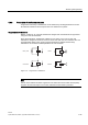
RF 300 system planning 4.6 EMC Guidelines 4.6.6 Prevention of interference sources A high level of immunity to interference can be achieved by avoiding interference sources. All switched inductances are a frequent source of interference in plants. Suppression of inductance Relays, contactors, etc. generate interference voltages and must therefore be suppressed using one of the circuits below.
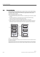
RF 300 system planning 4.6 EMC Guidelines 4.6.7 Equipotential bonding Potential differences between different parts of a plant can arise due to the different design of the plant components and different voltage levels. If the plant components are connected across signal cables, transient currents flow across the signal cables. These transient currents can corrupt the signals. Proper equipotential bonding is thus essential.
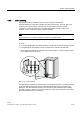
RF 300 system planning 4.6 EMC Guidelines 4.6.8 Cable shielding Signal cables must be shielded in order to prevent coupling of interference. The best shielding is achieved by installing the cables in steel tubes. However, this is only necessary if the signal cable is routed through an environment prone to particular interference. It is usually adequate to use cables with braided shields. In either case, however, correct connection is vital for effective shielding.
RF 300 system planning 4.6 EMC Guidelines Cable tie 5HPRYH SDLQW Figure 4-16 Connection of shielding bus The shielding bus must be connected to the PE busbar. If shielded cables have to be interrupted, the shield must be continued via the corresponding connector housing. Only suitable connectors may be used for this purpose.
Readers The reader ensures inductive communication with the transponders, and handles the serial connection to the communication modules/interface modules and 8xIQ-Sense module. Communication between the transponder and reader takes place over inductive alternating fields. The transmittable data volume between reader and transponder depends on: • the speed at which the transponder moves through the transmission window of the reader. • the length of the transmission window.
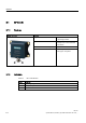
Readers 5.1 RF 310-R 5.1 5.1.1 5.1 RF 310-R Features Reader RF 310-R Features Design (1) IQ-Sense interface (2) Operating indicator Applications Identification tasks on small assembly lines in harsh industrial environments Read/write distance to transponder 30 mm max. Data transmission rate Read: 50 bytes/s Write: approx. 40 bytes/s 5.1.
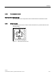
Readers 5.1 RF 310-R 5.1.3 Transmission window Ensuring reliable data exchange The "center point" of the transponder must be situated within the transmission window. 5.1.4 Metal-free area The RF 310-R can be flush-mounted in metal. Please allow for a possible reduction in the field data values.
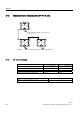
Readers 5.1 RF 310-R 5.1.5 Minimum distance between several RF 310-R units 5) 5 0LQLPXP GLVWDQFH IURP 5) 5 WR 5) 5 ' ุ PP ' ' 5) 5 Figure 5-2 5.1.
Readers 5.1 RF 310-R 5.1.7 Pin assignment of the IQ-Sense interface Table 5-2 RF 310-R pin assignment Pin Pin, device end, 4-pin M12 Assignment 1 IQ-Sense 2 Not assigned 3 IQ-Sense 4 Not assigned 5.1.8 Cable and connector pin assignment The following figure shows the cable and connector pin assignment of the connecting cable between 8xIQ-Sense and RF 310-R.
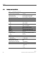
Readers 5.1 RF 310-R 5.1.9 Technical data of the RF 310-R Table 5-3 Technical data of the RF 310-R Inductive interface to the transponder Transmission frequency for power/data 13.56 MHz Interface to SIMATIC S7-300 IQ-Sense, 2-wire polarity independent Required master module 8-IQ-Sense (6ES7 338-7XF00-0AB0) RFID channels (RF 310-R) Max. 2 possible per master module Hybrid operation with other profiles Max. 4 Opto-BERO, 1x SIMATIC RF 310-R Cable length, reader Max.
Readers 5.1 RF 310-R 5.1.10 FCC information Siemens SIMATIC RF 300 FCC ID: xxxxxxxx This device complies with part 15 of the fcc rules. Operation is subject to the following two conditions: (1) This device may not cause harmful interference, and (2) This device must accept any interference received, including interference that may cause undesired operation.
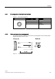
Readers 5.1 RF 310-R Dimension drawing 5.1.
Transponder/tags 6 Transponders consist predominantly of logic, FRAM and/or EEPROM. If a transponder moves into the transmission field of the reader, the necessary power for all of the circuit components is generated and monitored by the power supply unit. The pulsecoded information is prepared in such a way that it can be processed further as pure digital signals. The handling of data, including check routines, is performed by the control unit, which also manages the various memories.
Transponder/tags 6.1 RF 320-T 6.1 6.1.1 6.1 RF 320-T Features RF 320-T transponder Features Applications Identification tasks on small assembly lines in harsh industrial environments Memory Read-only area (4 bytes UID) User data area (20 bytes) Read/write range Max.
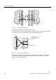
Transponder/tags 6.1 RF 320-T 6.1.2 Metal-free area Direct mounting of the RF 320-T on metal Direct mounting of the RF 320-T on metal is not allowed. The following figures show the minimum distance between the RF 320-T and metal: K ! PP 'DWD PHPRU\ 0HWDO 1RQ PHWDO Figure 6-1 Mounting of the RF 320-T on metal with spacer Flush-mounting of the RF 320-T in metal 0HWDO K ! PP 'DWD PHPRU\ 1RQ PHWDO D ! PP Figure 6-2 Flush-mounting of the RF 320-T in metal with spacer RF 300 System Manual,
Transponder/tags 6.1 RF 320-T 6.1.
Transponder/tags 6.1 RF 320-T 6.1.4 Technical data Table 6-3 Technical data of the RF 320-T Memory size 20 bytes EEPROM (r/w), 4 bytes UID (ro) Memory organization Byte-oriented access, write protection possible in 4-byte blocks MTBF 8 x 10⁶ h Read cycles Unlimited Write cycles, min. 50 000 at ≤ 40 °C, typical > 100 000 Data retention time > 10 years (at < +40 °C) Read/write distance, max.
Transponder/tags 6.1 RF 320-T 6.1.5 Ordering data RF 320-T transponder Order No. Transponder RF 320-T, button, 20-byte EEPROM 6GT2 800-1CA00 IP 67 -25 to +85 °C d = 27 mm x 4 mm 6.1.
Transponder/tags 6.2 RF 340-T 6.2 6.2.1 6.2 RF 340-T Features RF 340-T transponder Features Applications Memory Identification tasks on small assembly lines in harsh industrial environments Read-only area (4 bytes UID) Read/write memory (8 KB) Read/write range Max.
Transponder/tags 6.2 RF 340-T 6.2.2 Metal-free area Direct mounting of the RF 340-T on metal is allowed.
Transponder/tags 6.2 RF 340-T 6.2.
Transponder/tags 6.2 RF 340-T 6.2.4 Technical data Table 6-6 6-10 Technical data of the RF 340-T Memory size 8 KB Memory organization 8 bit / bytewise Memory configuration • Serial number (UID) • Application memory 4 bytes (fixed code) 8188 bytes r/w Storage technology FRAM MTBF, at +40 °C > 1.5 x 10⁶ h Write cycles, at +40°C Virtually unlimited (>1010) Read cycles Unlimited Transmission rate • Reading • Writing with RS 422 reader: with IQ-Sense reader: Approx. 0.3 ms / byte approx. 0.
Transponder/tags 6.2 RF 340-T 6.2.5 Ordering data Ordering data RF 340-T Order No. RF 340-T transponder 8 KB FRAM 6GT2 800-4BB00 48 x 25 x 15 mm (L x W x H) 6.2.
Transponder/tags 6.
Communication modules 7 The communication modules (interface modules) are links between the RFID components (reader and transponder) and the higher-level control systems (e.g. SIMATIC S7) or PC or computers.
Communication modules 7.1 8xIQ-Sense 7.1 7.1 8xIQ-Sense The 8xIQ-Sense module in conjunction with the RF 310-R handles the function of the communication module in SIMATIC RF 300. It can be operated centrally in an S7-300 or decentrally in an ET 200M. 7.1.
Communication modules 7.1 8xIQ-Sense 7.1.2 Indicators Status displays The 8xIQ-Sense module has the following LEDs: A green LED, which has no function for RFID devices, and a red SF LED (system fault LED), which indicates the diagnostic state of the module.
Communication modules 7.1 8xIQ-Sense 7.1.
Communication modules 7.1 8xIQ-Sense 7.1.4 Addressing The address range of the 8xIQ-Sense module is 16 bytes I/O. This is independent of the choice of channel profiles on the connected device (i.e. the IQ profile IDs in HW Config). Access to memory areas A direct association exists between the number of the channel to which the IQ-Sense device is connected (terminal) and the input and output data area of the module.
Communication modules 7.
Communication modules 7.1 8xIQ-Sense 7.1.5 Technical data Voltages and currents Rated supply voltage 24 V DC Reverse polarity protection yes Galvanic isolation • Between the channels • Between channels and backplane bus no yes Permissible potential difference Between different circuits 75 V DC / 60 V AC Insulation tested at 500 V DC Current input • from the backplane bus • from L+ power supply 120 mA typical Module power loss 2.5 W typical 500 mA max.
Communication modules 7.
Accessories 8.1 8.1 8 MOBY software Version 3.0 and higher of the "MOBY Software", product is supplied on CD. The software includes a complete set of function blocks and drivers for MOBY.
Accessories 8.1 MOBY software The "MOBY Software" CD has a user-friendly interface based on HTML. When you run start.exe, a window appears with the following main menu items: • FC for S7 • FB for S5 • PC Support • Doc • Tools • Demo • News Notes on MOBY software and licensing When purchasing an interface module or SIM, no software or documentation is supplied. The "MOBY Software" CD-ROM contains all available FBs/FCs for the SIMATIC, C libraries for Windows 98/NT, demo programs, etc.
A A Appendix A.1 A.1 Certificates and approvals DIN ISO 9001 certificate The quality assurance system for the entire product process (development, production, and marketing) at Siemens fulfills the requirements of ISO 9001 (corresponds to EN29001: 1987). This has been certified by DQS (the German society for the certification of quality management systems). EQ-Net certificate no.
Appendix A.1 Certificates and approvals EMC USA Federal Communications Commission Radio Frequency Interference Statement This equipment has been tested and found to comply with the limits for a Class A digital device, pursuant to Part 15 of the FCC Rules. These limits are designed to provide reasonable protection against harmful interference when the equipment is operated in a commercial environment.
Appendix A.2 Service and support A.2 A.2 Service and support Technical support You can reach the technical support team for all A&D projects at • Telephone: +49 (0) 180 5050 222 • Fax: +49 (0) 180 5050 223 Internet • Visit our site on the Internet at: http://www.siemens.com/automation/service&support • You can send a support query to: http://www.siemens.de/automation/support-request • You can find the latest general information about our identification systems on the Internet at: http://www.siemens.
Appendix A.4 Application consulting A.4 A.4 Application consulting For questions about special applications, please send an e-mail to the following address: application-consulting.FAS@siemens.com or call the following phone number: 0911/895-5775 A.5 A.5 Training Training center We offer appropriate courses to get you started. Please contact your regional Training Center, or the central Training Center in D-90327 Nuremberg. Telephone: +49 (911) 895-3200 http://www.sitrain.
List of abbreviations ASM Interface module CSA Canadian Standard Association EMC Electromagnetic compatibility FB Function Block FC Function IEC International Electrotechnical Commission L Length of a transmission window MDS Mobile data memory RFID Radio Frequency Identification Devices Sa Operating distance between MDS and SLG RF 300 System Manual, 05/2005, (4)J31069 D0166-U001-A1-7618, -- Glossary-1
List of abbreviations Sg Limit distance SLG Write/read device SP Intersection of the axes of symmetry of the MDS Tag See transponder TPDR Transponder UL Underwriter Laboratories, USA VDE Verband Deutscher Elektrotechniker [Association of German Electrical Engineers] XPDR Transponder Glossary-2 RF 300 System Manual, 05/2005, (4)J31069 D0166-U001-A1-7618, --
Glossary Active field Area with minimum field strength containing the transmission window, as well as the areas in which the field strength is no longer sufficient for data exchange. Active surface See active field Automation system (AS) A programmable logical controller (PLC) of the SIMATIC S7 system, comprising a central controller, a CPU and various I/O modules. Battery-free data memory Mobile data memories which operate without batteries.
Glossary Electromagnetic compatibility Electromagnetic compatibility is the ability of an electrical or electronic device to operate satisfactorily in an electromagnetic environment without affecting or interfering with the environment over and above certain limits. Equipotential bonding Potential differences between different parts of a plant can arise due to the different design of the plant components and different voltage levels.
Glossary Programmable logic controller (PLC) The programmable logical controllers (PLCs) of the SIMATIC S5 systems consist of a central controller, one or more CPUs, and various other modules (e.g. I/O modules). Read/write devices (SLG) See readers Read/write distance See transmission distance Reader/writer See write/read device RFID systems SIMATIC RF identification systems control and optimize material flow and production sequences.
Glossary Glossary-4 RF 300 System Manual, 05/2005, (4)J31069 D0166-U001-A1-7618, --
Index 8 8xIQ-Sense module, 7-2 Addressing, 7-5 Configuration, 7-4 Features, 7-2 Indicators, 7-3 Direction of motion Transponder, 4-4 Dwell time Transponder, 4-6 Dynamic mode, 4-5 Dynamic mode Dwell time of the transponder, 4-6 E A Active field, 4-2 Active surface, 4-4 Application consulting, A-4 Application Planning SIMATIC RF 300, 4-1 Approvals, A-1 C Cabinet configuration, 4-32 Calculation example, 4-9 Certificates, A-1 Communication, 4-7 between RF 300 components, 4-7 Communication modules 8xIQ-Sense
Index Installation guidelines, 4-14 Interference sources Electromagnetic, 4-30 IQ-Sense interface Pin assignment, 5-5 M Main applications RF 300, 3-2 Metal-free area Reader RF 310-R, 5-3 RF 320-T transponder, 6-3 RF 340-T transponder, 6-8 Minimum distance Reader to reader, 4-12 Transponder to transponder, 4-12 MOBY software, 8-1 Mounting options of transponders and readers, 4-18 O Ordering data Reader RF 340-T, 6-11 R Read/write distance, 4-2 Reader RF 310-R, 5-2 Cable and connector pin assignment, 5-5 D
Index U User data Calculation of maximum amount of, 4-7 RF 300 System Manual, 05/2005, (4)J31069 D0166-U001-A1-7618, -- Index-3
Index Index-4 RF 300 System Manual, 05/2005, (4)J31069 D0166-U001-A1-7618, --
Siemens AG Automation and Drives Special Products, Projects Automotive Industry, Training Postfach 4848 90327 NUERNBERG Federal Republic of Germany www.siemens.