Communication modules 7.
Communication modules 7.7 RF170C 7.7.4 Technical specifications Table 7-22 Technical specifications for RF170C Normal addressing Filehandler Serial interface to the user PROFIBUS DP-V1/PROFINET IO Interface to the ET 200pro ET 200pro backplane bus Connection method See ET 200pro operating instructions Transmission rate See ET 200pro operating instructions Max. block length 2 words cyclic/240 bytes acyclic (per channel) Serial interface to the reader/ write/read device Connector Max.
Communication modules 7.7 RF170C Normal addressing • RF170C with connection module Filehandler 90 x 130 x 60 Weight • RF170C communication module Approx. 270 g • RF170C connection module Approx. 500 g Degree of protection MTBF (at 40°C) Approvals IP67 129 years cULus (file E116536) 1) All supply and signal voltages must be low level protective voltage (SELV/PELV acc. to EN 60950) 24 V DC supply: Safety (electrical) isolation of low voltage (SELV / PELV acc.
Communication modules 7.7 RF170C 7.7.5 Dimensional drawings RF170C with connection module The dimension drawing for an RF170C communication module with plugged-in connection module is shown below.
Communication modules 7.7 RF170C 7.7.6 Ordering data Communication module and connection module Table 7-23 Communication module and connection module order numbers Name Order number RF170C communication module, 1 unit 6GT2002-0HD00 RF170C connection module, 1 unit 6GT2002-1HD00 RF170C connection module accessories Table 7-24 Order numbers for RF170C connection module accessories Name Write/read device cable MOBY I / E / U Order number 2.0 m 6GT2091-0FH20 5.
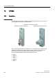
Communication modules 7.8 RF180C 7.8 RF180C 7.8.1 Description Area of application The RF180C communication module is a module that can be used on any controller for operating RFID components over PROFINET IO. RF180C communication module With M12 connection block (7/8") With push-pull connection block When operating the RF180C on a SIMATIC S7, a convenient function module is made available to the user (FB 45).
Communication modules 7.8 RF180C Features Up to two readers / SLGs can be operated on the RF180C at the same time. The user can issue a command to 2 readers / SLGs simultaneously (FB 45 when operating on a SIMATIC S7). The tag data are accessed by means of physical addressing of the tag. In SIMATIC S7, the FB 45 is available for this purpose.
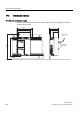
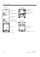
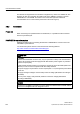
Communication modules 7.8 RF180C &RQQHFWLRQ EORFN 0 6,0$7,& 5) & %DVLF XQLW ; *7 -' &RQQHFWRU VRFNHW IRU VW UHDGHU 6/* ; ; 0 FRQQHFWLRQ VRFNHWV IRU 352),1(7 ,2 &RQQHFWLRQ EORFN FRQQHFWLRQ VRFNHWV IRU YROWDJH VXSSO\ 6WDWXV /('V IRU RSHUDWLRQ RI WKH VW UHDGHU 6/* ; ; &RQQHFWRU VRFNHW IRU QG UHDGHU 6/* ; 6WDWXV /('V IRU RSHUDWLRQ RI WKH QG UHDGHU 6/* 6WDWXV /('V IRU LQWHUIDFH PRGXOH &RQQHFWLRQ EORFN 3XVK SXOO *7 -' *7 -' ;
Communication modules 7.8 RF180C Potential Ungrounded installation of the system is possible with the RF180C. The following circuit shows the internal relationships of the reference potentials.
Communication modules 7.8 RF180C The RF180C is integrated into the hardware configuration by means of a GSDML file. The RF180C can then be configured using HW-Config of the SIMATIC manager or another PROFINET tool. The GSDML file can be found on the RFID Systems Software & Documentation CD or on the Internet (see Section Service & Support). 7.8.2 Connection Proper use When connecting non-specified devices to the RF180C, it is possible that the connected device may be destroyed.
Communication modules 7.8 RF180C PROFINET IO installation techniques PROFINET IO communication can be established in BUS or STAR topology. Please note the information in the Section Loop-through connection of PROFINET IO and supply voltage.
Communication modules 7.8 RF180C Reader/SLG connection system One reader/SLG always occupies one M12 connection socket on the RF180C. A preassembled cable therefore provides the optimum easy connection for the reader/SLG. The connection cable is 2 m long in the standard version.
Communication modules 7.8 RF180C 7.8.2.1 Wiring connection block M12, 7/8" Features ● Connect the supply voltages and PROFINET IO to connection block M12, 7/8": – M12 connection in D coding: PROFINET IO – 7/8" connection: Supply voltages ● You can loop the supply voltages and PROFINET IO through via the second M12 or 7/8" round socket. Requirements ● Wire connection block M12, 7/8" when the supply voltage is switched off.
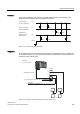
Communication modules 7.8 RF180C Wiring M12, 7/8" connector The tables below contain the pin assignment for the M12 and 7/8" connectors: Table 7-25 Pin assignment for M12 connector, 4-pole, D coding (PROFINET IO) Pin Assignment 1 Data line TxP 2 Data line RxP 3 Data line TxN 4 Data line RxN View of M12 connector, 4-pole, D coding (wiring side) (LQVSHLVHQ XQG :HLWHUVFKOHLIHQ 352),1(7 ,2 ; ; (WKHUQHW .
Communication modules 7.8 RF180C Connecting M12, 7/8" connectors 1. Press the connector (M12 or 7/8") into the relevant round socket on the connection block. Ensure that the correct stop is provided between the connector and bush (groove and spring). 2. Use the knurled locking ring to secure the connector.
Communication modules 7.8 RF180C 7.8.3 Parameter assignment 7.8.3.1 PROFINET IO configuration Introduction The GSDML file allows you to configure RF180C in STEP 7 V5.3 + SP 2 or higher. The GSDML file must have been installed beforehand in the configuration software. Requirements ● A GSDML file is required to integrate the RF180C into the hardware configuration of the SIMATIC Manager: GSDML-V1.0-SIEMENS-RF180C-"Datum im Format yyyymmdd".
Communication modules 7.8 RF180C 7.8.3.2 Assigning device names to the I/O device Introduction Each PROFINET IO device is assigned a unique device ID by the manufacturer (MAC address). Each RF180C IO device is addressed by its device name in the configuration and user program. For detailed information on addressing in PROFINET IO, refer to the PROFINET System Description.
Communication modules 7.8 RF180C Station flash test If you use more than one IO device, the dialog also displays more than one IO device. In this case, you should compare the MAC address of the device with the indicated MAC address and select the proper IO device. The identification of IO devices in a system is facilitated by a node flash test. The flash test is activated as follows: 1. In the Edit Ethernet Node dialog, select one of the indicated IO devices. 2. Press the button .
Communication modules 7.8 RF180C 7.8.3.3 Configuration parameters of the RF180C The GSDML file contains four parameters relevant to RFID that must be set. They are set by selecting the "Object properties" for slot 0 of the RF180C in HW Config The parameters are described in the function manual FB 45.
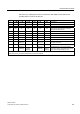
Communication modules 7.8 RF180C 7.8.3.4 Input parameters for RF180C Input parameters for RF180C with FB 45 Allocation is undertaken in UDT 10. Table 7-28 Input parameters for RF180C with FB 45 Address +0.0 Name ASM_address Comment Each RF180C occupies four bytes of I/O in the I/O area of the controller ASM_channel Permissible values 256, 260, 264, 268, ... 1, 2 +2.0 +8.0 MDS_control B#16#0, 1 0 = no presence check 1 = presence check +9.0 ECC_mode TRUE, FALSE +9.
Communication modules 7.8 RF180C 7.8.3.5 Command table of the RF180C Table of commands of the RF180C for standard addressing (FB 45) Allocation is undertaken in UDT 20 using the "command" variable.
Communication modules 7.8 RF180C 7.8.4 PROFINET diagnostics 7.8.4.1 Diagnosis using LEDs The following figure shows details of the LEDs of the RF180C.
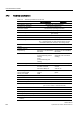
Communication modules 7.8 RF180C Table 7-30 Status LEDs for the RF180C LEDs Meaning* ON Lights up when the RF180C has completed start-up without errors. 24 VDC Lights up when the 24 V supply voltage is connected to the RF180C. ACT_1, ACT_2 The corresponding reader/SLG is active in processing a user command. ERR_1, ERR_2 * A flashing pattern indicates the last error to occur. PRE_1, PRE_2 ** Indicates the presence of a tag/MDS. RxD_1, RxD_2 Indicates live communication with the reader / SLG.
Communication modules 7.
Communication modules 7.8 RF180C 7.8.4.2 Parameterization of the diagnostics ● Faults are reported by PROFINET IO through the generation of alarms. Alarms are output using OB82. The alarm data can be accessed through SFB 54. Parameterizing possibilities See also Section Configuration parameters of RF180C. ● None An alarm will not be issued in the event of an error.
Communication modules 7.8 RF180C 7.8.4.3 Structure of the diagnostic data The header of a diagnostic data record comprises 20 bytes of PROFINET IO-specific data. The manufacturer-specific diagnostic data start from Byte 21. For the RF180C, the diagnostic data are structured in accordance with the PROFIBUS Profile Guideline (PROFIBUS Proxy Guideline, Identification Systems Proxy Ident Function Block) for identification systems with MOBY-specific additional information.
Communication modules 7.8 RF180C 7.8.
Communication modules 7.8 RF180C Ambient temperature During operation 0 to +60 °C Transport and storage –40 to +70 °C Dimensions (W x H x D) in mm Base unit only 60 x 210 x 30 Base unit with M12, 7/8" connection block 60 x 210 x 54 Basic unit with push-pull connection block 60 x 216 x 100 Weight Base unit Approx. 210 g M12, 7/8" connection block Approx. 230 g Push-pull connection block Approx.
Communication modules 7.8 RF180C 7.8.
Communication modules 7.
Communication modules 7.8 RF180C 7.8.7 Connecting cable to the reader/SLG 7.8.7.
Communication modules 7.
Communication modules 7.8 RF180C 7.8.7.2 Self-assembled cable A reader/SLG connector plug with screw terminals is provided for users who want to individually pre-assemble their own cables (refer to the relevant system manual). Cables and reader/SLG connector plugs can be ordered from the Catalog FS 10 Sensors for Production Automation. Cable structure You will need cables of the following specifications for self-assembled cables: 7 x 0.25 mm2 LiYC11Y 7 x 0.
Communication modules 7.8 RF180C 7.8.8 Ordering data Table 7-39 RF180C ordering data and accessories RF180C RF180C communication module max.
Communication modules 7.
Communication modules 7.
8 System diagnostics 8.
System diagnostics 8.2 Diagnostics functions 8.2 Diagnostics functions 8.2.1 Overview Extended diagnostic functions with SIMATIC RF300 With SIMATIC RF300, extended diagnostic functions are available which simplify start-up and maintenance. These diagnostic data are accessed using the FC 45 function with the SLG STATUS and MDS STATUS commands. These two commands can each be called in various modes (subcommands) for which corresponding data structures (UDTs) are defined.
System diagnostics 8.2 Diagnostics functions 8.2.2 Reader diagnostics with SLG STATUS The SLG STATUS command can be used to scan the status and diagnostics data of the reader.
System diagnostics 8.
System diagnostics 8.2 Diagnostics functions 8.2.3 Transponder diagnostics with MDS STATUS The MDS STATUS command can be used to scan the status and diagnostics data of the transponder that is located within the antenna field. MDS STATUS (mode 01), UDT260 UID Binary value 0 … 264 -1 = b0-31: 4 byte TAG ID, b32-63: 0 MDS type Binary value 0x01 = Transponder without FRAM 0x02 = Transponder with FRAM 8 KB 0x03 = Transponder with FRAM 32 KB 0 … 255 = Content of lock-bit register (EEPROM addr.
System diagnostics 8.
9 Accessories CD "RFID Systems Software & Documentation" The CD contains: ● FB/FC for SIMATIC, 3964R ● Driver for DOS/Windows 95/NT/2000/XP ● C libraries ● PC demonstration program ● RFID documentation in PDF format, especially RFID system manuals, programming instructions and operating instructions The "RFID Systems Software & Documentation" CD has a user-friendly interface based on HTML. After Start.
Accessories Note Notes on "RFID system software" and licensing When purchasing a communication module or an interface module, no software or documentation is supplied. The "RFID Systems Software & Documentation" CD-ROM contains all available FBs/FCs for the SIMATIC, C libraries, demo programs, etc. and needs to be ordered separately. In addition, the CD-ROM contains the complete RFID documentation (German, English and French) in PDF format.
A Appendix A.1 Certificates and Approvals DIN ISO 9001 certificate The quality assurance system for the entire product process (development, production, and marketing) at Siemens fulfills the requirements of ISO 9001 (corresponds to EN29001: 1987). This has been certified by DQS (the German society for the certification of quality management systems). EQ-Net certificate no.
Appendix A.1 Certificates and Approvals Certifications for the United States, Canada, and Australia Safety One of the following markings on a device is indicative of the corresponding approval: Underwriters Laboratories (UL) per UL 60950 (I.T.E) or per UL 508 (IND.CONT.EQ) Underwriters Laboratories (UL) according to Canadian standard C22.2 No. 60950 (I.T.E) or C22.2 No. 142 (IND.CONT.EQ) Underwriters Laboratories (UL) according to standard UL 60950, Report E11 5352 and Canadian standard C22.2 No.
Appendix A.1 Certificates and Approvals EMC USA Federal Communications Commission Radio Frequency Interference Statement This equipment has been tested and found to comply with the limits for a Class A digital device, pursuant to Part 15 of the FCC Rules. These limits are designed to provide reasonable protection against harmful interference when the equipment is operated in a commercial environment.
Appendix A.2 Service & Support A.2 Service & Support Technical Support You can reach the technical support team for all A&D projects at ● Phone: +49 (0) 180 5050 222 ● Fax: +49 (0) 180 5050 223 Internet ● You can contact us via the Internet at: http://www.siemens.com/automation/service&support ● We will gladly respond to any support queries at: http://www.siemens.com/automation/support-request ● You can find the latest general information about our identification systems on the Internet at: http://www.
Appendix A.4 Training A.4 Training Training center We offer appropriate courses to get you started. Please contact your local Training Center or the Central Training Center in D-90327 Nuremberg. Telephone: +49 (911) 895-3200 http://www.siemens.
Appendix A.
Glossary Active surface Area with minimum field strength containing the transmission window, as well as the areas in which the field strength is no longer sufficient for data exchange. Automation system (AS) A programmable logical controller (PLC) of the SIMATIC S7 system, comprising a central controller, a CPU and various I/O modules. Battery-free data storage unit Mobile data storage units which operate without batteries.
Glossary Dynamic mode In dynamic mode, the data carrier moves past the read/write device at a traversing rate which depends on the configuration. Various checking mechanisms (listen-in check, CRC, ECC, etc.) ensure error-free data transfer even under extreme environmental conditions. A serial connection (up to 1000 m) is used to connect the read/write device directly to an interface module, PC, or any other system.
Glossary Limit distance The limit distance is the maximum clear distance between the upper surface of the read/write device and the transponder, at which the transmission can still function under normal conditions. M Centerpoint of a field of a transmission window Metal-free area Distance/area which must be maintained between the transponder and metal in order to prevent interference during data transfer between the transponder and read/write device.
Glossary RFID systems SIMATIC RF identification systems control and optimize material flow and production sequences. They identify reliably, quickly and economically, use non-contact data communication technology, and store data directly on the product. They are also resistant to contamination. Secondary fields The strength of the secondary fields, which exist in addition to the transmission window, is usually lower than that of the transmission window and depends on the metallic environment.
Index 8 8xIQ-Sense module Addressing, 168 Configuration, 166 Indicators, 165 Ordering data, 170 A Active surface, 28 Application Planning SIMATIC RF300, 23 Approvals, 265 ASM 452 Configuration, 173 Indicators, 172 Operating mode, 174 Ordering data, 180 Pin assignments, 172 PROFIBUS address and terminating resistor, 176 PROFIBUS configuration, 173 Reader connection system, 174 ASM 456 Cable, 190 Cable assembly by the customer, 191 Cable lengths, 190 Configurations, 184 Design, 183 Dimensional drawing with E
Index D Degree of protection IP65, IP66, IP67 M12 caps, 219 Design Centralized, 166 Distributed, 167 Diagnostic functions Readers, 259 SIMATIC RF300, 258 Transponder, 261 Diagnostics with LED display RF170C, 220 Dimension drawing RF170C with connection module, 224 Direction of motion Transponder, 28 Display elements Reader RF340R, 100 RF310R reader with RS422 interface, 94 Dwell time Transponder, 30 Dynamic mode, 29 Dwell time of the transponder, 30 E Electromagnetic compatibility Coupling paths, 79 Elect
Index Reader to reader, 42 Transponder to transponder, 42 O Ordering data 8xIQ-Sense module, 170 Communication module, 225 Connection module, 225 RF310R with IQ-Sense, 91 P PROFIBUS cable Stripped lengths, 203 R Reader RF310R, 88, 93, 105, 118 Features, 88, 93, 105, 118 Metal-free area, 89, 94 Minimum distance, 89, 95 Pin assignment of IQ-Sense interface, 88, 167 Reader RF340R, 99 Features, 99 Metal-free area, 100, 119 Readers, 87 Mounting, 58 Reducing interference due to metal, 57 Reduction of field da
Index Tolerance, 28 Tracking tolerances, 28 Training center, 269 Transmission gaps, 39 Transmission window ANT18 and ANT30 (RF350R), 26 Impact of metal, 60 Reader RF340R, 25 Reduction of field data, 60 RF310R reader and ANT1 (RF350R), 24 RF380R reader, 27 Width, 28 Transponder, 125 Active surface, 28 Directions of motion, 28 Dwell time, 30 Mounting on metal, 59 Resistance to chemicals, 66 Transponder RF320T Features, 126 Metal-free area, 127 Technical data, 128 Transponder RF340T Features, 130 Metal-free a
Get more Information www.siemens.com/simatic-sensors Siemens AG Industry Sector Postfach 48 48 90026 NÜRNBERG DEUTSCHLAND www.siemens.