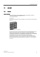
Communication modules 7.3 ASM 452 7.3 ASM 452 7.3.1 Features Area of application The ASM 452 interface module is a MOBY module for operating MOBY and RF300 components with RS422 over PROFIBUS DP-V1 on ● Any computers and PCs ● Any PLCs When operating the interface module on a SIMATIC S7, function blocks are made available to the user. Figure 7-6 Interface module ASM 452 The ASM 452 is the result of consistent development of the familiar ASM 450/451 interface modules.
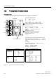
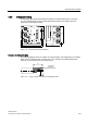
Communication modules 7.3 ASM 452 7.3.2 Pin assignment and display elements Pin assignments The figure below illustrates the pin assignments of ASM 452. /('V IRU 352),%86 '3 $60 6) %) ; ; ; ; ; )DXOW )DXOW 21 /LJKWV XS ZKHQ WKHUH LV $60 LV JHQHUDWHG E\ WKH 9 VXSSO\ YROWDJH 9 '& /LJKWV XS ZKHQ WKH 9 VXSSO\ YROWDJH LV FRQQHFWHG WR WKH $60 6) %) 21 '& 9 6/*
Communication modules 7.3 ASM 452 7.3.3 Configuration Configuration Hardware description The ASM 452 has the same housing as the distributed I/O system ET 200X. General information on ASM 452 (e.g. assembly, operation and wiring; general technical data) is available in the ET200X manual (Order No. 6ES7 198-8FA00-8AA0). Descriptions of accessories and network components can also be found in this manual.
Communication modules 7.3 ASM 452 PROFIBUS configuration The ASM 452 is integrated into the hardware configuration by means of a GSD file. The ASM can then be configured using the HW Config of SIMATIC Manager or another PROFIBUS tool. A GSD file is provided for ASM 452 on the CD "RFID Systems Software & Documentation". Operating mode of the ASM 452 The approved operating modes of ASM 452 are described in the GSD file. It is set using the hardware configuration tool (e.g. STEP 7 HW Config).
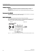
Communication modules 7.3 ASM 452 Cable installation Signal M12 (reader side) Cable X1 / Data X2 24 V DC 1 Pink - 1 TX - 2 Yellow 4 - GND 3 Gray - 3 TX + 4 Green 1 - RX + 5 white 2 - RX - 6 brown 3 - - - 8 + terminal piece Shield 5 5 Shield Cable assignment ASM 452/473 ↔ RF3xxR reader with RS422 (6GT2891-1CH20) A reader cable connector with screw-type terminals is provided for users who want to individually pre-assemble their own cables (see figure below).
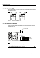
Communication modules 7.3 ASM 452 PROFIBUS cable with 24 V supply The ASM 452 can also be operated with the "green" PROFIBUS cable. It is important to ensure that a 24 V cable is connected from X12 to X13. The 24 V cable can be connected to pins 5 and 6 in plug X12. ; ; Figure 7-11 ; ; ; ; PROFIBUS cable with 24 V supply PROFIBUS address and terminating resistor You must remove the connector plate from the ASM before you set the PROFIBUS address or connect the terminating resistor.
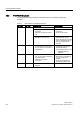
Communication modules 7.3 ASM 452 7.3.4 Technical data Table 7-3 Technical data for ASM 452 ASM 452 with FC 45 Serial interface to the user PROFIBUS DP-V1 Procedure after connection EN 50170 Vol. 2 PROFIBUS PG 11 cable gland PROFIBUS and power supply connectors are not included in the scope of delivery Transmission rate 9600 baud to 12 Mbaud (automatic detection) Max. block length 2 words cyclic/240 bytes acyclic Serial interface to the RF3xxR Connector 2 x M12 coupler plug Max.
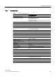
Communication modules 7.3 ASM 452 7.3.5 PROFIBUS Diagnosis The following table lists possible error indications with their meanings and provides remedies. Table 7-4 LED indication for PROFIBUS diagnosis "BF" LED "SF"LED Cause of error ON * • ASM 452 is in start-up mode. • The connection to the DP master • has failed. ASM 452 not detecting a baud • rate. Check the PROFIBUS DP connection. Check the DP master.
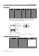
Communication modules 7.3 ASM 452 7.3.6 Dimension drawing The following figure shows the dimensional drawing of an ASM 452 with bus connectors. You must add the length of the PG cable gland and the radius of the cable used to the measured overall width and depth. Figure 7-13 Dimensional drawing of ASM 452 Example of stripped lengths The following diagram shows an example of stripped lengths.
Communication modules 7.3 ASM 452 7.3.7 Ordering data Table 7-5 Ordering data for ASM 452 and accessories Product description Order No.
Communication modules 7.4 ASM 456 7.4 ASM 456 7.4.1 Description Field of application The ASM 456 interface modules are slave modules for operating RF300 components via the PROFIBUS DP/DP-V1 on any control systems. Figure 7-15 Interface module ASM 456 with ECOFAST connection block or M12, 7/8" When operating the interface module on a SIMATIC S7, convenient function blocks are made available to the user.
Communication modules 7.4 ASM 456 Features The ASM 456 replaces the ASM 452 in terms of functionality and provides a simplified connection system. You can continue to use the user software from ASM 452. Optimum data throughput can be achieved through acyclic data traffic on the PROFIBUS DP V1 even when using large PROFIBUS configurations. The minimum cyclic data load of the ASM 456 on the PROFIBUS provides the user with the guarantee that other PROFIBUS consumers (e.g.
Communication modules 7.4 ASM 456 Design The ASM 456 has the same housing as the distributed I/O system ET 200eco. The ASM has a connection block for connecting up to the PROFIBUS DP which is available as an option and the ECOFAST version or M12, 7/8". 02%< $60 The following figure shows the basic design of the ASM 456.
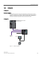
Communication modules 7.4 ASM 456 Configuration The following figure shows how the ASM 456 is integrated in an automation system. 352),%86 '3 PDVWHU PRGXOH H J 6 &38 $60b ; ; P 352),%86 FDEOHV 9 IRU $60 DQG UHDGHU WR RWKHU 352),%86 QRGHV 6,0$7,& 6,0$7,& 5) 5 5) 5 5HDGHU 5HDGHU 6,0$7,& 5) 7 6WDQGDUG FDEOH OHQJWK Figure 7-17 6,0$7,& 5) 7 7UDQVSRQGHU ASM 456 configurator The ASM 456 is integrated into the hardware configuration by means of a GSD file.
Communication modules 7.4 ASM 456 7.4.2 Setting the PROFIBUS address Features The PROFIBUS address defines the address at which the ASM 456 distributed I/O system is found on the PROFIBUS DP. Requirements ● The PROFIBUS DP address for the ASM 456 is set on the connection block. ● Each address can be assigned only once on the PROFIBUS DP. ● The PROFIBUS address set must match the PROFIBUS address defined in the configuring software (for the ASM 456).
Communication modules 7.4 ASM 456 Setting PROFIBUS DP addresses on connection block M12, 7/8” Valid PROFIBUS DP addresses are 1 to 99. 1. Remove the two seal caps from the rotary switches (if necessary, use a 14 mm socket wrench). 2. Set the required PROFIBUS address on the rotary switches using a screwdriver. – Lower rotary switch: 1st position – Upper rotary switch: 10th position 3. Screw the two seal caps back onto the rotary switches (torque: 0.5 Nm to 0.8 Nm.
Communication modules 7.4 ASM 456 Setting PROFIBUS DP addresses on connection block ECOFAST Valid PROFIBUS DP addresses are 1 to 99. 1. Loosen the screw connection of the configuration plug with the ECOFAST connection block and remove the plug. Figure 7-19 Loosening the configuration plug's screw connection 2. Loosen the screw connection for the cover cap on the configuration plug and remove the latter. 3. Set the PROFIBUS address using the DIL switches.
Communication modules 7.4 ASM 456 7.4.
Communication modules 7.4 ASM 456 Wiring M12, 7/8" connector The tables below contain the connector assignment for the M12, 7/8" connector: Table 7-7 Connection assignment for M12 connector (PROFIBUS DP) Pin Assignment View of M12 connector (wiring side) 1 Supply positive (P5V2) * 2 Data line A (RxD / TxD-N) 3 Data reference potential (M5V2) * 4 Data line B (RxD / TxD-P) 5 Shield 6XSSO\ '3 6LJQDO $ JUHHQ 6KLHOG Thread Shield 6LJQDO % UHG /RRS WKURXJK FRQQHFWLRQ '3 %XV F
Communication modules 7.4 ASM 456 Note When connecting up the supply voltage, we recommend that the cable 6XV1 822-5B... (5 x 1.5 mm2 pre-assembled with 7/8" connectors) is used. If you want to assemble the cable yourself, then the conductor cross-section should be 1.5 mm2. Connecting the ASM 456 up to protective earth 1. Isolate the grounding cable and secure the cable lug. 2. Screw the cable lug down to the ASM 456 (M5 retaining bolt). The torque is 3 Nm.
Communication modules 7.4 ASM 456 Cable assembly by the customer A reader connection plug with screw-type terminals is available for users who want to make their own cables. Cables and reader cable connectors can be ordered according to the MOBY catalog. For self-assembled cables, you will need cable to the following specifications: 7 x 0.25 mm2 LiYC11Y 7 x 0.25 M12 connectors can be purchased from appropriate electrical retailers (e.g. Binder in Germany).
Communication modules 7.4 ASM 456 7.4.4 Diagnosis using LEDs 02%< $60 The following figure shows details of the LEDs of the ASM 456. ; $&7B 35(B 5HDGHU 5['B (55B $&7B 35(B 5HDGHU 5['B (55B ; 352),%86 *7 (' 6) Figure 7-23 LEDs of the ASM 456 Table 7-10 Status LEDs for ASM 456 LEDs ON 24 V DC ACT_1, ACT_2 %) 21 '& 9 Meaning* Lights up when there is logic voltage at the ASM (is generated by the 24 V supply voltage.
Communication modules 7.4 ASM 456 Table 7-11 LED display for PROFIBUS diagnosis BF SF On – flashes On Cause of error Error handling • ASM is in start-up mode. – • • Connection to DP Master failed. ASM not detecting a baud rate • • • Bus interrupt DP Master not functioning • • The project data sent to the ASM by the DP Master do not match the configuration of the ASM. • • • • flashes – • • On flashes • Check the PROFIBUS DP connection.
Communication modules 7.4 ASM 456 7.4.5 Technical data Table 7-12 Technical data for ASM 456 Serial interface to the user PROFIBUS DP-V1 Procedure after connection EN 50170 Vol. 2 PROFIBUS M12 and 7/8" technology / ECOFAST Transmission rate 9600 baud to 12 Mbaud (automatic detection) Max. block length 2 words cyclic/240 bytes acyclic Serial interface to the reader • Connector 2 x M12 coupler plug • Max.
Communication modules 7.4 ASM 456 7.4.6 Dimension drawing The following figure shows the dimensional drawing of an ASM 456 with bus connection block.
Communication modules 7.4 ASM 456 7.4.7 Ordering data Table 7-13 Ordering data for ASM 456 and accessories Product description Order No. ASM 456 interface module for PROFIBUS DP V1 max.
Communication modules 7.5 ASM 473 7.5 ASM 473 7.5.1 Features Field of application The ASM 473 interface module is an RF300 module for SIMATIC S7. It can be plugged into the ET 200X distributed I/O station and DESINA. ET 200X is operated by the user over PROFIBUS DP V1. An S7-300 or S7-400 with integrated PROFIBUS connection can be used as the controller. ASM 473 supplements the SIMATIC S7 interface module ASM 475.
Communication modules 7.5 ASM 473 7.5.2 Pin assignment and display elements Pin assignments The figure below illustrates the pin assignment for the read/write device and the display elements.
Communication modules 7.5 ASM 473 7.5.3 Configuration 352),%86 '3 PDVWHU PRGXOH H J 6 &38 FRQQHFWLRQ RI D QRQ 6LHPHQV PDVWHU SRVVLEOH VRRQ 352),%86 FDEOHV %DVLF PRGXOH (7 ; %0 (7 ; %0 '(6,1$ %0 WR RWKHU 352),%86 QRGHV 9 VXSSO\ IRU (7 ; (OHFWURQLFV 5) [[5 6,0$7,& 5) 5 9 VXSSO\ IRU 5) [[5 5) [[7 6,0$7,& 5) 7 Figure 7-27 Example - Configurator for ASM 473 Note It differs from ASM 452 in that for ET 200X the 24 V supply must be connected to the PROFIBUS
Communication modules 7.5 ASM 473 Basic module - Requirements for operation of ASM 473 The following table indicates the status of the ET 200X basic module of 10/2002. The functionality of new basic modules is stored in HW Config of the SIMATIC Manager.
Communication modules 7.5 ASM 473 Example for a maximum configuration of ASM-473 on an ET 200X 0D[ $60 FDQ EH RSHUDWHG LQ DQ (7 ; 6,0$7,& 6,0$7,& 6,0$7,& 6,0$7,& 6,0$7,& 6,0$7,& 6,0$7,& 5) 5 5) 5 5) 5 5) 5 5) 5 5) 5 5) 5 5) [[5 5) [[7 6,0$7,& 5) 7 Figure 7-28 Example for a maximum configuration of ASM 473 on an ET 200X Depending on the PROFIBUS master, up to 123 ET 200X modules can be run on one PROFIBUS branch.
Communication modules 7.5 ASM 473 7.5.4 Technical data Table 7-15 Technical specifications for ASM 473 Interface for ET 200X SIMATIC S7 I/O bus cyclic/acyclic services Communication 2 words cyclic/238 bytes acyclic Command buffer in ASM 142 x 238 bytes Serial interface to the reader • Connector 2 x M12 coupler plug • Max.
Communication modules 7.5 ASM 473 7.5.5 Dimensional drawings Dimension drawing for mounting holes The figure below shows the dimensions for the position of the holes for the fixing screws for a basic module and an ASM 473 expansion module.
Communication modules 7.5 ASM 473 7.5.6 Ordering data Table 7-16 Ordering data for ASM 473 and accessories Product description Order No. Interface module ASM 473 1x RF3xxR reader with RS422 interface 6GT2002-0HA10 Accessories: Connecting cable ASM 473 ↔ Reader RF3xxR Plug-in cable, pre-assembled, length 2 m (standard length) 6GT2891-1CH20 Plug-in cable, pre-assembled, length 5 m 6GT2891-1CH50 Opt.
Communication modules 7.6 ASM 475 7.6 ASM 475 7.6.1 Features Area of application The ASM 475 interface module acting as the link between all RF300 systems and SIMATIC S7-300 performs the functions of a communication module. It can be operated centrally in the S7-300 or decentrally in an ET200M. As many as eight ASM 475 interface modules can be plugged into one SIMATIC S7-300 rack and operated. In a configuration with several racks (max. four), the ASM 475 can be plugged into and operated on any rack.
Communication modules 7.6 ASM 475 7.6.2 Indicators Bezel and indicator elements The figure below illustrates the bezel of the ASM 475 and the inside of the front door complete with the associated connection diagram. The read/write devices must be connected to the ASM in accordance with the connection diagram. 02%< $60 6) 9 '& (55B 6 35(B 6 ( ( $&7B (55B 35(B 6 6 ( ( 6/*b 5['B 6/*b $&7B 5['B *7 b *$ 6WDWXV DQG HUURU GLVSOD\V Figure 7-32 206 &RQQHFWLRQ
Communication modules 7.6 ASM 475 Display elements on the ASM Table 7-17 Function of the LEDs on the ASM 475 Light emitting diode Meaning SF System fault (hardware error on ASM) DC 5V 24 V are connected to ASM and the 5 V voltage on ASM is OK. ACT_1, ACT_2 The corresponding reader is active in processing a user command. ERR_1, ERR_2 A flashing pattern indicates the last error to occur. This display can be reset using the parameter Option 1. PRE_1, PRE_2 Indicates the presence of a transponder.
Communication modules 7.6 ASM 475 7.6.
Communication modules 7.6 ASM 475 Distributed configuration with ET200M $60b 2WKHU PRGXOHV IURP WKH 6 UDQJH LQFOXGLQJ $60 (7 0 $60 FKDQQHO 5HDGHU 5HDGHU 5HDGHU ZLWK 56 LQWHUIDFH 6,0$7,& 6,0$7,& 5) 5 5) 5 6,0$7,& 6,0$7,& 5) 7 5) 7 7UDQVSRQGHU Figure 7-34 7UDQVSRQGHU Configurator for ASM 475 with RF310R reader (distributed configuration) Reader connection system $60 VLGH 5HDGHU VLGH &DEOH ZLWK HQG VOHHYHV JUD\ SLQN \HOORZ EURZQ
Communication modules 7.
Communication modules 7.6 ASM 475 7.6.4 Technical data Table 7-19 Technical data for ASM 475 ASM 475 with FC 45 Serial interface for SIMATIC S7-300 or ET200M I/O bus; cyclic and acyclic services Communication 2 words cyclic/238 bytes acyclic Command buffer in ASM 475 70 x 238 bytes per RF310R reader Serial interface to the reader Connector Via screw-type terminal on front connector The front connector is not included in the scope of supply. Max.
Communication modules 7.6 ASM 475 7.6.5 Ordering data Table 7-20 Ordering data for ASM 475 and accessories Product description Order No.
Communication modules 7.7 RF170C 7.7 RF170C 7.7.1 Description Area of application The RF170C communication module is a SIMATIC S7 module. It can be plugged into the ET 200pro distributed I/O device. The ET 200pro is operated by the user over PROFIBUS DP-V1 or PROFINET IO. An S7-300 or S7-400 with integrated PROFIBUS/PROFINET connection can be used as the controller. The ET 200pro with RF170C can communicate with all DP masters compliant with the IEC 61784-1:2002 Ed1 CP 3/1 standard.
Communication modules 7.7 RF170C Features Operation of the RF170C requires an ET 200pro interface module (IM 154-1 DP, IM 1542 DP High Feature, IM 154-4 PN High Feature, IM 154-8 CPU). Via the RF170C: the data on the transponders can be ● physically addressed (normal addressing) or ● addressed by means of a DOS-like file management system (filehandler).
Communication modules 7.7 RF170C Design The ET 200pro is designed for rack mounting and always features ● an interface module which transfers data to the DP master or IO controller, ● or a CPU, ● up to 9 RF170C modules, ● connection modules in various designs for – interface modules (PROFIBUS DP, PROFINET IO, power supply) – Communication modules You can thus set the focus of your configuration on local requirements.
Communication modules 7.7 RF170C Figure 7-37 ET 200pro with RF170C ① Rack ② Interface module with bus module ③ RF170C communication module (comprising electronic module and bus module) ④ Terminating module ⑤ RF170C connection module ⑥ Connection module for interface module An IM 154-8 CPU can also be inserted as interface module.
Communication modules 7.7 RF170C Configuration Note In the figures below, the ET 200pro with the CM IM DP Direct connection module represents an example for the interface module.
Communication modules 7.7 RF170C 7.7.2 Connect the RF170C with the connection module Introduction On the RF170C connection module, you connect the cable to the readers / write/read devices using 8-pin round sockets. Use an 8-pin M12 connector and a corresponding cable if you prefer to produce a customized cable. In doing so, please comply with the cable configurator in the system manuals of the RFID families.
Communication modules 7.7 RF170C Connect RF170C connection module 1. Insert the RF170C connection module into the communication module. 2. Screw the connection module onto the rack (4 cross-head screws on the front: top and bottom, tightening torque 1.5 Nm) Figure 7-41 Connect RF170C connection module Sealing unused sockets Always close all unused sockets using M12 caps in order to achieve the degree of protection IP65, IP66 or IP67.
Communication modules 7.7 RF170C 7.7.3 LED displays on the RF170C communication module LED display The figure below shows the position and layout of the LED display on the the RF170C connection module. Figure 7-42 LED display on the RF170C communication module Status and error LEDs on the RF170C connection module Table 7-21 Status and error LEDs for RF170C LEDs SF ACT_1, ACT_2 Meaning* Group errors The corresponding reader / (write/read device) is active in processing a user command.