
User's Manual Part 1
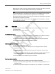
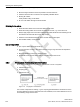
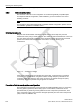

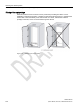
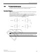
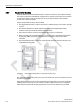
Table Of Contents
- SIMATIC RF300
- Legal information
- Table of contents
- 1 Introduction
- 2 Safety information
- 3 System overview
- 4 Planning the RF300 system
- 4.1 Fundamentals of application planning
- 4.1.1 Selection criteria for SIMATIC RF300 components
- 4.1.2 Transmission window and read/write distance
- 4.1.3 Width of the transmission window
- 4.1.4 Impact of secondary fields
- 4.1.5 Setup help of the readers of the second generation
- 4.1.6 Permissible directions of motion of the transponder
- 4.1.7 Operation in static and dynamic mode
- 4.1.8 Dwell time of the transponder
- 4.1.9 Communication between communications module, reader and transponder
- 4.2 Field data for transponders, readers and antennas
- 4.3 Installation guidelines
- 4.4 Chemical resistance of the transponders
- 4.5 Guidelines for electromagnetic compatibility (EMC)
- 4.1 Fundamentals of application planning
- 5 Readers
- 5.1 SIMATIC RF310R
- 5.2 SIMATIC RF310R with Scanmode
- 5.2.1 Features
- 5.2.2 Ordering data for RF310R with Scanmode
- 5.2.3 Pin assignment RF310R special version Scanmode RS-422 interface
- 5.2.4 LED operating display
- 5.2.5 Ensuring reliable data exchange
- 5.2.6 Metal-free area
- 5.2.7 Minimum distance between several readers
- 5.2.8 Technical specifications
- 5.2.9 Approvals
- 5.2.10 Dimension drawing
- 5.3 SIMATIC RF310R - second generation
- 5.4 SIMATIC RF340R/RF350R
- 5.4.1 SIMATIC RF340R
- 5.4.1.1 Features
- 5.4.1.2 Ordering data for RF340R
- 5.4.1.3 Pin assignment of RF340R RS422 interface
- 5.4.1.4 LED operating display
- 5.4.1.5 Ensuring reliable data exchange
- 5.4.1.6 Metal-free area
- 5.4.1.7 Minimum distance between RF340R readers
- 5.4.1.8 Technical specifications
- 5.4.1.9 Approvals
- 5.4.1.10 Dimension drawing
- 5.4.2 SIMATIC RF350R
- 5.4.3 Use of the reader in hazardous areas
- 5.4.1 SIMATIC RF340R
- 5.5 SIMATIC RF340R/RF350R - second generation
- 5.6 SIMATIC RF380R
- 5.6.1 Features
- 5.6.2 RF380R ordering data
- 5.6.3 Pin assignment of RF380R RS-232/RS-422 interface
- 5.6.4 LED operating display
- 5.6.5 Ensuring reliable data exchange
- 5.6.6 Metal-free area
- 5.6.7 Minimum distance between RF380R readers
- 5.6.8 Technical specifications
- 5.6.9 Approvals
- 5.6.10 Use of the reader in hazardous areas
- 5.6.11 Use of the reader in hazardous areas for gases
- 5.6.12 Installation and operating conditions for the hazardous area
- 5.6.13 Dimension drawing
- 5.7 SIMATIC RF380R with Scanmode
- 5.7.1 Features
- 5.7.2 Ordering data for RF380R with Scanmode
- 5.7.3 Pin assignment RF380R Scanmode RS-232 interface
- 5.7.4 LED operating display
- 5.7.5 Ensuring reliable data exchange
- 5.7.6 Metal-free area
- 5.7.7 Minimum distance between several RF380R Scanmode readers
- 5.7.8 Technical specifications
- 5.7.9 Approvals
- 5.7.10 Certificates and Approvals
- 5.7.11 Dimension drawing
- 5.8 SIMATIC RF382R with Scanmode
- 5.8.1 Characteristics
- 5.8.2 RF382R with Scanmode ordering data
- 5.8.3 Pin assignment RF382R Scanmode RS232 interface
- 5.8.4 LED operating display
- 5.8.5 Ensuring reliable data exchange
- 5.8.6 Mounting on metal
- 5.8.7 Minimum distance between several RF382R Scanmode readers
- 5.8.8 Transmission window
- 5.8.9 Technical specifications
- 5.8.10 Approvals
- 5.8.11 Dimensional diagram

Planning the RF300 system
4.5 Guidelines for electromagnetic compatibility (EMC)
SIMATIC RF300
106 System Manual, 07/2016, C79000-G8976-C345-0x
4.5.5
Cabinet configuration
The influence of the user in the configuration of an electromagnetically compatible plant
encompasses cabinet configuration, cable installation, ground connections and correct
shielding of cables.
Note
For information about electromagnetically compatible cabinet configuration, please cons
ult
the installation guidelines for SIMATIC PLCs.
Shielding by enclosure
Magnetic and electrical fields and electromagnetic waves can be kept away from the
interference sink by using a metal enclosure. The easier the induced interference current can
flow, the greater the intrinsic weakening of the interference field. All enclosures and metal
panels in the cabinet should therefore be connected in a manner allowing good
conductance.
Figure 4-13 Shielding by enclosure
If the control cabinet panels are insulated from each other, a high-frequency-conducting
connection can be established using ribbon cables and high-frequency terminals or HF
conducting paste. The larger the area of the connection, the greater the high-frequency
conductivity. This is not possible using single-wire connections.
Prevention of interference by optimum configuration
Good interference suppression can be achieved by installing SIMATIC PLCs on conducting
mounting plates (unpainted). When setting up the control cabinet, interference can be
prevented easily by observing certain guidelines. Power components (transformers, drive
units, load power supply units) should be arranged separately from the control components
(relay control unit, SIMATIC S7).