
User's Manual Part 1
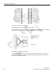
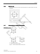
Table Of Contents
- SIMATIC RF300
- Legal information
- Table of contents
- 1 Introduction
- 2 Safety information
- 3 System overview
- 4 Planning the RF300 system
- 4.1 Fundamentals of application planning
- 4.1.1 Selection criteria for SIMATIC RF300 components
- 4.1.2 Transmission window and read/write distance
- 4.1.3 Width of the transmission window
- 4.1.4 Impact of secondary fields
- 4.1.5 Setup help of the readers of the second generation
- 4.1.6 Permissible directions of motion of the transponder
- 4.1.7 Operation in static and dynamic mode
- 4.1.8 Dwell time of the transponder
- 4.1.9 Communication between communications module, reader and transponder
- 4.2 Field data for transponders, readers and antennas
- 4.3 Installation guidelines
- 4.4 Chemical resistance of the transponders
- 4.5 Guidelines for electromagnetic compatibility (EMC)
- 4.1 Fundamentals of application planning
- 5 Readers
- 5.1 SIMATIC RF310R
- 5.2 SIMATIC RF310R with Scanmode
- 5.2.1 Features
- 5.2.2 Ordering data for RF310R with Scanmode
- 5.2.3 Pin assignment RF310R special version Scanmode RS-422 interface
- 5.2.4 LED operating display
- 5.2.5 Ensuring reliable data exchange
- 5.2.6 Metal-free area
- 5.2.7 Minimum distance between several readers
- 5.2.8 Technical specifications
- 5.2.9 Approvals
- 5.2.10 Dimension drawing
- 5.3 SIMATIC RF310R - second generation
- 5.4 SIMATIC RF340R/RF350R
- 5.4.1 SIMATIC RF340R
- 5.4.1.1 Features
- 5.4.1.2 Ordering data for RF340R
- 5.4.1.3 Pin assignment of RF340R RS422 interface
- 5.4.1.4 LED operating display
- 5.4.1.5 Ensuring reliable data exchange
- 5.4.1.6 Metal-free area
- 5.4.1.7 Minimum distance between RF340R readers
- 5.4.1.8 Technical specifications
- 5.4.1.9 Approvals
- 5.4.1.10 Dimension drawing
- 5.4.2 SIMATIC RF350R
- 5.4.3 Use of the reader in hazardous areas
- 5.4.1 SIMATIC RF340R
- 5.5 SIMATIC RF340R/RF350R - second generation
- 5.6 SIMATIC RF380R
- 5.6.1 Features
- 5.6.2 RF380R ordering data
- 5.6.3 Pin assignment of RF380R RS-232/RS-422 interface
- 5.6.4 LED operating display
- 5.6.5 Ensuring reliable data exchange
- 5.6.6 Metal-free area
- 5.6.7 Minimum distance between RF380R readers
- 5.6.8 Technical specifications
- 5.6.9 Approvals
- 5.6.10 Use of the reader in hazardous areas
- 5.6.11 Use of the reader in hazardous areas for gases
- 5.6.12 Installation and operating conditions for the hazardous area
- 5.6.13 Dimension drawing
- 5.7 SIMATIC RF380R with Scanmode
- 5.7.1 Features
- 5.7.2 Ordering data for RF380R with Scanmode
- 5.7.3 Pin assignment RF380R Scanmode RS-232 interface
- 5.7.4 LED operating display
- 5.7.5 Ensuring reliable data exchange
- 5.7.6 Metal-free area
- 5.7.7 Minimum distance between several RF380R Scanmode readers
- 5.7.8 Technical specifications
- 5.7.9 Approvals
- 5.7.10 Certificates and Approvals
- 5.7.11 Dimension drawing
- 5.8 SIMATIC RF382R with Scanmode
- 5.8.1 Characteristics
- 5.8.2 RF382R with Scanmode ordering data
- 5.8.3 Pin assignment RF382R Scanmode RS232 interface
- 5.8.4 LED operating display
- 5.8.5 Ensuring reliable data exchange
- 5.8.6 Mounting on metal
- 5.8.7 Minimum distance between several RF382R Scanmode readers
- 5.8.8 Transmission window
- 5.8.9 Technical specifications
- 5.8.10 Approvals
- 5.8.11 Dimensional diagram

Readers
5.1 SIMATIC RF310R
SIMATIC RF300
118 System Manual, 07/2016, C79000-G8976-C345-0x
RF310R face-of-face
D
≥ 300 mm
Figure 5-3 Face-of-face distance between two RF310Rs
5.1.8
Technical specifications
Table 5- 3 Technical specifications of the RF310R reader with RS-422 interface
6GT2801-1AB10
Product type designation
SIMATIC RF310R
Radio frequencies
Operating frequency, rated value
13.56 MHz
Electrical data
Maximum range
60 mm
Maximum data transmission speed
reader ↔ transponder
RF300 transponder ISO transponder
• Read • approx. 8000
bytes/s
• approx. 1500
bytes/s
• Write • approx. 8000
bytes/s
• approx. 1500
bytes/s
Transmission speed
19.2, 57.6, 115.2 kBd
Read/write distances of the reader See section "Field data for transponders, readers
and antennas (Page 48)."
MTBF (Mean Time Between Failures)
170 years
Interfaces
Electrical connector design
M12, 8-pin
Standard for interfaces for communication
RS-422
Antenna
integrated