
User's Manual Part 1
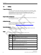
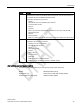


Table Of Contents
- SIMATIC RF300
- Legal information
- Table of contents
- 1 Introduction
- 2 Safety information
- 3 System overview
- 4 Planning the RF300 system
- 4.1 Fundamentals of application planning
- 4.1.1 Selection criteria for SIMATIC RF300 components
- 4.1.2 Transmission window and read/write distance
- 4.1.3 Width of the transmission window
- 4.1.4 Impact of secondary fields
- 4.1.5 Setup help of the readers of the second generation
- 4.1.6 Permissible directions of motion of the transponder
- 4.1.7 Operation in static and dynamic mode
- 4.1.8 Dwell time of the transponder
- 4.1.9 Communication between communications module, reader and transponder
- 4.2 Field data for transponders, readers and antennas
- 4.3 Installation guidelines
- 4.4 Chemical resistance of the transponders
- 4.5 Guidelines for electromagnetic compatibility (EMC)
- 4.1 Fundamentals of application planning
- 5 Readers
- 5.1 SIMATIC RF310R
- 5.2 SIMATIC RF310R with Scanmode
- 5.2.1 Features
- 5.2.2 Ordering data for RF310R with Scanmode
- 5.2.3 Pin assignment RF310R special version Scanmode RS-422 interface
- 5.2.4 LED operating display
- 5.2.5 Ensuring reliable data exchange
- 5.2.6 Metal-free area
- 5.2.7 Minimum distance between several readers
- 5.2.8 Technical specifications
- 5.2.9 Approvals
- 5.2.10 Dimension drawing
- 5.3 SIMATIC RF310R - second generation
- 5.4 SIMATIC RF340R/RF350R
- 5.4.1 SIMATIC RF340R
- 5.4.1.1 Features
- 5.4.1.2 Ordering data for RF340R
- 5.4.1.3 Pin assignment of RF340R RS422 interface
- 5.4.1.4 LED operating display
- 5.4.1.5 Ensuring reliable data exchange
- 5.4.1.6 Metal-free area
- 5.4.1.7 Minimum distance between RF340R readers
- 5.4.1.8 Technical specifications
- 5.4.1.9 Approvals
- 5.4.1.10 Dimension drawing
- 5.4.2 SIMATIC RF350R
- 5.4.3 Use of the reader in hazardous areas
- 5.4.1 SIMATIC RF340R
- 5.5 SIMATIC RF340R/RF350R - second generation
- 5.6 SIMATIC RF380R
- 5.6.1 Features
- 5.6.2 RF380R ordering data
- 5.6.3 Pin assignment of RF380R RS-232/RS-422 interface
- 5.6.4 LED operating display
- 5.6.5 Ensuring reliable data exchange
- 5.6.6 Metal-free area
- 5.6.7 Minimum distance between RF380R readers
- 5.6.8 Technical specifications
- 5.6.9 Approvals
- 5.6.10 Use of the reader in hazardous areas
- 5.6.11 Use of the reader in hazardous areas for gases
- 5.6.12 Installation and operating conditions for the hazardous area
- 5.6.13 Dimension drawing
- 5.7 SIMATIC RF380R with Scanmode
- 5.7.1 Features
- 5.7.2 Ordering data for RF380R with Scanmode
- 5.7.3 Pin assignment RF380R Scanmode RS-232 interface
- 5.7.4 LED operating display
- 5.7.5 Ensuring reliable data exchange
- 5.7.6 Metal-free area
- 5.7.7 Minimum distance between several RF380R Scanmode readers
- 5.7.8 Technical specifications
- 5.7.9 Approvals
- 5.7.10 Certificates and Approvals
- 5.7.11 Dimension drawing
- 5.8 SIMATIC RF382R with Scanmode
- 5.8.1 Characteristics
- 5.8.2 RF382R with Scanmode ordering data
- 5.8.3 Pin assignment RF382R Scanmode RS232 interface
- 5.8.4 LED operating display
- 5.8.5 Ensuring reliable data exchange
- 5.8.6 Mounting on metal
- 5.8.7 Minimum distance between several RF382R Scanmode readers
- 5.8.8 Transmission window
- 5.8.9 Technical specifications
- 5.8.10 Approvals
- 5.8.11 Dimensional diagram

SIMATIC RF300
System Manual, 07/2016, C79000-G8976-C345-0x
13
Introduction
1
1.1
Navigating in the system manual
Structure of the content
Content
Contents Detailed organization of the documentation, including the index of pages and chapters
Introduction
Purpose, structure and description of the important topics.
Safety Information Refers to all the valid technical safety aspects which have to be adhered to while installing,
commissioning and operating from the product/system view and with reference to statutory
regulations.
System overview
Overview of all RF identification systems, system overview of SIMATIC RF300
Planning the RF300 system Information about possible applications of SIMATIC RF300, support for application plan-
ning, tools for finding suitable SIMATIC RF300 components.
Reader
Description of readers which can be used for SIMATIC RF300
Antennas
Description of antennas which can be used for SIMATIC RF300
RF300 transponder
Description of RF300 transponders which can be used for SIMATIC RF300
ISO transponder
Description of ISO transponders which can be used for SIMATIC RF300
System integration Overview of the communications modules and function blocks that can be used for
SIMATIC RF300
System diagnostics
Description of system diagnostics available for SIMATIC RF300
Appendix
• Certificates and approvals
• Accessories
• Connecting cables
• Ordering data
• Service & Support