
User's Manual Part 1
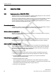
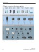

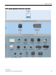
Table Of Contents
- SIMATIC RF300
- Legal information
- Table of contents
- 1 Introduction
- 2 Safety information
- 3 System overview
- 4 Planning the RF300 system
- 4.1 Fundamentals of application planning
- 4.1.1 Selection criteria for SIMATIC RF300 components
- 4.1.2 Transmission window and read/write distance
- 4.1.3 Width of the transmission window
- 4.1.4 Impact of secondary fields
- 4.1.5 Setup help of the readers of the second generation
- 4.1.6 Permissible directions of motion of the transponder
- 4.1.7 Operation in static and dynamic mode
- 4.1.8 Dwell time of the transponder
- 4.1.9 Communication between communications module, reader and transponder
- 4.2 Field data for transponders, readers and antennas
- 4.3 Installation guidelines
- 4.4 Chemical resistance of the transponders
- 4.5 Guidelines for electromagnetic compatibility (EMC)
- 4.1 Fundamentals of application planning
- 5 Readers
- 5.1 SIMATIC RF310R
- 5.2 SIMATIC RF310R with Scanmode
- 5.2.1 Features
- 5.2.2 Ordering data for RF310R with Scanmode
- 5.2.3 Pin assignment RF310R special version Scanmode RS-422 interface
- 5.2.4 LED operating display
- 5.2.5 Ensuring reliable data exchange
- 5.2.6 Metal-free area
- 5.2.7 Minimum distance between several readers
- 5.2.8 Technical specifications
- 5.2.9 Approvals
- 5.2.10 Dimension drawing
- 5.3 SIMATIC RF310R - second generation
- 5.4 SIMATIC RF340R/RF350R
- 5.4.1 SIMATIC RF340R
- 5.4.1.1 Features
- 5.4.1.2 Ordering data for RF340R
- 5.4.1.3 Pin assignment of RF340R RS422 interface
- 5.4.1.4 LED operating display
- 5.4.1.5 Ensuring reliable data exchange
- 5.4.1.6 Metal-free area
- 5.4.1.7 Minimum distance between RF340R readers
- 5.4.1.8 Technical specifications
- 5.4.1.9 Approvals
- 5.4.1.10 Dimension drawing
- 5.4.2 SIMATIC RF350R
- 5.4.3 Use of the reader in hazardous areas
- 5.4.1 SIMATIC RF340R
- 5.5 SIMATIC RF340R/RF350R - second generation
- 5.6 SIMATIC RF380R
- 5.6.1 Features
- 5.6.2 RF380R ordering data
- 5.6.3 Pin assignment of RF380R RS-232/RS-422 interface
- 5.6.4 LED operating display
- 5.6.5 Ensuring reliable data exchange
- 5.6.6 Metal-free area
- 5.6.7 Minimum distance between RF380R readers
- 5.6.8 Technical specifications
- 5.6.9 Approvals
- 5.6.10 Use of the reader in hazardous areas
- 5.6.11 Use of the reader in hazardous areas for gases
- 5.6.12 Installation and operating conditions for the hazardous area
- 5.6.13 Dimension drawing
- 5.7 SIMATIC RF380R with Scanmode
- 5.7.1 Features
- 5.7.2 Ordering data for RF380R with Scanmode
- 5.7.3 Pin assignment RF380R Scanmode RS-232 interface
- 5.7.4 LED operating display
- 5.7.5 Ensuring reliable data exchange
- 5.7.6 Metal-free area
- 5.7.7 Minimum distance between several RF380R Scanmode readers
- 5.7.8 Technical specifications
- 5.7.9 Approvals
- 5.7.10 Certificates and Approvals
- 5.7.11 Dimension drawing
- 5.8 SIMATIC RF382R with Scanmode
- 5.8.1 Characteristics
- 5.8.2 RF382R with Scanmode ordering data
- 5.8.3 Pin assignment RF382R Scanmode RS232 interface
- 5.8.4 LED operating display
- 5.8.5 Ensuring reliable data exchange
- 5.8.6 Mounting on metal
- 5.8.7 Minimum distance between several RF382R Scanmode readers
- 5.8.8 Transmission window
- 5.8.9 Technical specifications
- 5.8.10 Approvals
- 5.8.11 Dimensional diagram

System overview
3.2 SIMATIC RF300
SIMATIC RF300
28 System Manual, 07/2016, C79000-G8976-C345-0x
Note
Note on operation of the transponders MDS D5xx and MDS E6xx
Note that the transponders MDS D5xx and MDS E6xx can only be operated in conjunction
with the readers of t
he second generation (article number "6GT2801-xBAxx").