
User's Manual Part 1
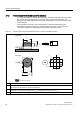
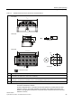
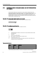
Table Of Contents
- Titel
- SIMATIC Sensors RFID systems SIMATIC RF300
- Legal Information
- Table of contents
- 1 Introduction
- 2 Safety information
- 3 System overview
- 4 RF300 system planning
- 4.1 Fundamentals of application planning
- 4.1.1 Selection criteria for SIMATIC RF300 components
- 4.1.2 Transmission window and read/write distance
- 4.1.3 Width of the transmission window
- 4.1.4 Impact of secondary fields
- 4.1.5 Permissible directions of motion of the transponder
- 4.1.6 Operation in static and dynamic mode
- 4.1.7 Dwell time of the transponder
- 4.1.8 Communication between communication module, reader (with IQ-Sense interface) and transponder
- 4.1.9 Calculation example (IQ-Sense)
- 4.1.10 Communication between communication module, reader (with RS422 interface) and transponder
- 4.1.11 Calculation example (RS422)
- 4.2 Field data for transponders, readers and antennas
- 4.3 Relationship between the volume of data and the transponder speed
- 4.4 Installation guidelines
- 4.5 Chemical resistance of the transponders
- 4.6 EMC Directives
- 4.1 Fundamentals of application planning
- 5 Readers
- 5.1 Overview
- 5.2 RF310R with IQ-Sense interface
- 5.2.1 Features
- 5.2.2 Pin assignment of RF310R IQ-Sense interface
- 5.2.3 Display elements of the RF310R reader with IQ-Sense interface
- 5.2.4 Ensuring reliable data exchange
- 5.2.5 Metal-free area
- 5.2.6 Minimum distance between RF310R readers
- 5.2.7 Technical data for RF310R reader with IQ-Sense interface
- 5.2.8 FCC information
- 5.2.9 Ordering data of RF310R with IQ-Sense interface
- 5.2.10 Dimension drawing

RF300 system planning
4.1 Fundamentals of application planning
SIMATIC RF300
System Manual, 09/2007, J31069 D0166-U001-A5-7618
23
Table 4-2 RF340R reader transmission window and read/write distance
s
0
/
[
PD[
/
\
PD[
/
[PD[
6
DPLQ
6
J
6
D
/
\
/
[
/
\PD[
6
DPLQ
/
[
/
\
6,(0(16
6,0$7,&
5)7
5)7
7UDQVSRQGHU
7UDQVSRQGHU
63
3ODQYLHZ
7UDQVPLVVLRQZLQGRZ
6LGHYLHZ
)URQWYLHZ
All dimensions in mm.
S
a
: Operating distance between transponder and reader
S
g
Limit distance (maximum clear distance between upper surface of the reader and the transponder, at which the
transmission can still function under normal conditions)
L
x
Length of a transmission window in the x direction
The length L
x
is valid for the calculation. At S
a,min
, the field length increases from L
x
to L
max
.
L
y
Length of a transmission window in the y direction
The length L
y
is valid for the calculation. At S
a,min
, the field length increases from L
y
to L
y max
.
M Field centerpoint