
User's Manual Part 1
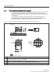
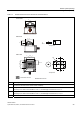
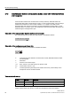
Table Of Contents
- Titel
- SIMATIC Sensors RFID systems SIMATIC RF300
- Legal Information
- Table of contents
- 1 Introduction
- 2 Safety information
- 3 System overview
- 4 RF300 system planning
- 4.1 Fundamentals of application planning
- 4.1.1 Selection criteria for SIMATIC RF300 components
- 4.1.2 Transmission window and read/write distance
- 4.1.3 Width of the transmission window
- 4.1.4 Impact of secondary fields
- 4.1.5 Permissible directions of motion of the transponder
- 4.1.6 Operation in static and dynamic mode
- 4.1.7 Dwell time of the transponder
- 4.1.8 Communication between communication module, reader (with IQ-Sense interface) and transponder
- 4.1.9 Calculation example (IQ-Sense)
- 4.1.10 Communication between communication module, reader (with RS422 interface) and transponder
- 4.1.11 Calculation example (RS422)
- 4.2 Field data for transponders, readers and antennas
- 4.3 Relationship between the volume of data and the transponder speed
- 4.4 Installation guidelines
- 4.5 Chemical resistance of the transponders
- 4.6 EMC Directives
- 4.1 Fundamentals of application planning
- 5 Readers
- 5.1 Overview
- 5.2 RF310R with IQ-Sense interface
- 5.2.1 Features
- 5.2.2 Pin assignment of RF310R IQ-Sense interface
- 5.2.3 Display elements of the RF310R reader with IQ-Sense interface
- 5.2.4 Ensuring reliable data exchange
- 5.2.5 Metal-free area
- 5.2.6 Minimum distance between RF310R readers
- 5.2.7 Technical data for RF310R reader with IQ-Sense interface
- 5.2.8 FCC information
- 5.2.9 Ordering data of RF310R with IQ-Sense interface
- 5.2.10 Dimension drawing

RF300 system planning
4.1 Fundamentals of application planning
SIMATIC RF300
30 System Manual, 09/2007, J31069 D0166-U001-A5-7618
4.1.8 Communication between communication module, reader (with IQ-Sense interface)
and transponder
Communication between the communication module (IQ-Sense), RF310R reader and
transponder takes place in fixed telegram cycles. 3 cycles of approximately 3 ms are always
needed for the transfer of a read or write command. 1 or 2 bytes of user data can be
transferred with each of these commands. The acknowledgement transfer (status or read
data) takes place in 3 further cycles. The transponder must be present within the field of the
reader during the message frame cycle.
Calculation of the communication time for interference-free transfer
The communication time for fault-free data transfer is calculated as follows:
=+ ⋅tKtn
KByte
(n >1)
Calculation of the maximum amount of user data
The maximum amount of user data is calculated as follows:
t
K
Communication time between communication module, RF310R IQ-Sense reader
and transponder
t
V
Dwell time
n Amount of user data in bytes
n
max
Max. amount of user data in bytes in dynamic mode
t
Byte
Transmission time for 1 byte
K Constant (internal system time) This contains the time for power buildup on the
transponder and for command transfer
Time constants K and t
Byte
K (ms) t
Byte
(ms) Command
15 15 Read (FRAM/EEPROM area)
15 15 Write (FRAM area)
30 30 Write (EEPROM area)
The table of time constants applies to every command. If a user command consists of
several subcommands, the above t
K
formula must be applied to each subcommand.