
User's Manual Part 1
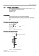
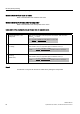
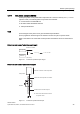
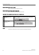
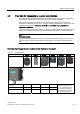
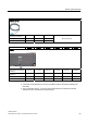
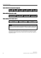
Table Of Contents
- Titel
- SIMATIC Sensors RFID systems SIMATIC RF300
- Legal Information
- Table of contents
- 1 Introduction
- 2 Safety information
- 3 System overview
- 4 RF300 system planning
- 4.1 Fundamentals of application planning
- 4.1.1 Selection criteria for SIMATIC RF300 components
- 4.1.2 Transmission window and read/write distance
- 4.1.3 Width of the transmission window
- 4.1.4 Impact of secondary fields
- 4.1.5 Permissible directions of motion of the transponder
- 4.1.6 Operation in static and dynamic mode
- 4.1.7 Dwell time of the transponder
- 4.1.8 Communication between communication module, reader (with IQ-Sense interface) and transponder
- 4.1.9 Calculation example (IQ-Sense)
- 4.1.10 Communication between communication module, reader (with RS422 interface) and transponder
- 4.1.11 Calculation example (RS422)
- 4.2 Field data for transponders, readers and antennas
- 4.3 Relationship between the volume of data and the transponder speed
- 4.4 Installation guidelines
- 4.5 Chemical resistance of the transponders
- 4.6 EMC Directives
- 4.1 Fundamentals of application planning
- 5 Readers
- 5.1 Overview
- 5.2 RF310R with IQ-Sense interface
- 5.2.1 Features
- 5.2.2 Pin assignment of RF310R IQ-Sense interface
- 5.2.3 Display elements of the RF310R reader with IQ-Sense interface
- 5.2.4 Ensuring reliable data exchange
- 5.2.5 Metal-free area
- 5.2.6 Minimum distance between RF310R readers
- 5.2.7 Technical data for RF310R reader with IQ-Sense interface
- 5.2.8 FCC information
- 5.2.9 Ordering data of RF310R with IQ-Sense interface
- 5.2.10 Dimension drawing

RF300 system planning
4.1 Fundamentals of application planning
SIMATIC RF300
36 System Manual, 09/2007, J31069 D0166-U001-A5-7618
Minimum distance from reader to reader
Refer to the field data of the reader for this value.
Minimum distance from transponder to transponder
Refer to the field data of the transponder for this value.
Calculation of the maximum amount of user data in dynamic mode
Step Formula/calculation
1. Calculate dwell time of the
transponder
Refer to the "Field data of all transponders and readers" table for value L.
Value V
Tag
= 1,00 m/s
v
t
v
⋅ ⋅
= = ==
L 0,8
0,038 m 0,8
0,0304 s
1,0 m/s
30,4 ms
Tag
2. Calculate maximum user data (n
max)
for reading or writing
(FRAM area)
Take value t
v
from Step 1.
Take values K and t
Byte
from Table "Time constants K and t
Byte
".
UHDGZULWH
max
168,46 168
Byte
v
t K 30,4ms 8,5ms
n Byte
t 0,13ms
− −
= =
⇒
=
Result
A maximum of 168 bytes can be read or written when passing the transponder.