
User's Manual Part 1

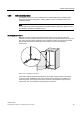
Table Of Contents
- Titel
- SIMATIC Sensors RFID systems SIMATIC RF300
- Legal Information
- Table of contents
- 1 Introduction
- 2 Safety information
- 3 System overview
- 4 RF300 system planning
- 4.1 Fundamentals of application planning
- 4.1.1 Selection criteria for SIMATIC RF300 components
- 4.1.2 Transmission window and read/write distance
- 4.1.3 Width of the transmission window
- 4.1.4 Impact of secondary fields
- 4.1.5 Permissible directions of motion of the transponder
- 4.1.6 Operation in static and dynamic mode
- 4.1.7 Dwell time of the transponder
- 4.1.8 Communication between communication module, reader (with IQ-Sense interface) and transponder
- 4.1.9 Calculation example (IQ-Sense)
- 4.1.10 Communication between communication module, reader (with RS422 interface) and transponder
- 4.1.11 Calculation example (RS422)
- 4.2 Field data for transponders, readers and antennas
- 4.3 Relationship between the volume of data and the transponder speed
- 4.4 Installation guidelines
- 4.5 Chemical resistance of the transponders
- 4.6 EMC Directives
- 4.1 Fundamentals of application planning
- 5 Readers
- 5.1 Overview
- 5.2 RF310R with IQ-Sense interface
- 5.2.1 Features
- 5.2.2 Pin assignment of RF310R IQ-Sense interface
- 5.2.3 Display elements of the RF310R reader with IQ-Sense interface
- 5.2.4 Ensuring reliable data exchange
- 5.2.5 Metal-free area
- 5.2.6 Minimum distance between RF310R readers
- 5.2.7 Technical data for RF310R reader with IQ-Sense interface
- 5.2.8 FCC information
- 5.2.9 Ordering data of RF310R with IQ-Sense interface
- 5.2.10 Dimension drawing

RF300 system planning
4.6 EMC Directives
SIMATIC RF300
System Manual, 09/2007, J31069 D0166-U001-A5-7618
73
4.6.2 What does EMC mean?
The increasing use of electrical and electronic devices is accompanied by:
● Higher component density
● More switched power electronics
● Increasing switching rates
● Lower power consumption of components due to steeper switching edges
The higher the degree of automation, the greater the risk of interaction between devices.
Electromagnetic compatibility (EMC) is the ability of an electrical or electronic device to
operate satisfactorily in an electromagnetic environment without affecting or interfering with
the environment over and above certain limits.
EMC can be broken down into three different areas:
● Intrinsic immunity to interference:
immunity to internal electrical disturbance
● Immunity to external interference:
immunity to external electromagnetic disturbance
● Degree of interference emission:
emission of interference and its effect on the electrical environment
All three areas are considered when testing an electrical device.
The RFID modules are tested for conformity with the limit values required by the CE and
RTTE guidelines. Since the RFID modules are merely components of an overall system, and
sources of interference can arise as a result of combining different components, certain
guidelines have to be followed when setting up a plant.
EMC measures usually consist of a complete package of measures, all of which need to be
implemented in order to ensure that the plant is immune to interference.
Note
The plant manufacturer is responsible for the observance of the EMC guidelines; the plant
operator is responsible for radio interference suppression in the overall plant.
All measures taken when setting up the plant prevent expensive retrospective modifications
and interference suppression measures.
The plant operator must comply with the locally applicable laws and regulations. They are
not covered in this document.