
User's Manual Part 1

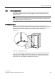
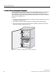
Table Of Contents
- Titel
- SIMATIC Sensors RFID systems SIMATIC RF300
- Legal Information
- Table of contents
- 1 Introduction
- 2 Safety information
- 3 System overview
- 4 RF300 system planning
- 4.1 Fundamentals of application planning
- 4.1.1 Selection criteria for SIMATIC RF300 components
- 4.1.2 Transmission window and read/write distance
- 4.1.3 Width of the transmission window
- 4.1.4 Impact of secondary fields
- 4.1.5 Permissible directions of motion of the transponder
- 4.1.6 Operation in static and dynamic mode
- 4.1.7 Dwell time of the transponder
- 4.1.8 Communication between communication module, reader (with IQ-Sense interface) and transponder
- 4.1.9 Calculation example (IQ-Sense)
- 4.1.10 Communication between communication module, reader (with RS422 interface) and transponder
- 4.1.11 Calculation example (RS422)
- 4.2 Field data for transponders, readers and antennas
- 4.3 Relationship between the volume of data and the transponder speed
- 4.4 Installation guidelines
- 4.5 Chemical resistance of the transponders
- 4.6 EMC Directives
- 4.1 Fundamentals of application planning
- 5 Readers
- 5.1 Overview
- 5.2 RF310R with IQ-Sense interface
- 5.2.1 Features
- 5.2.2 Pin assignment of RF310R IQ-Sense interface
- 5.2.3 Display elements of the RF310R reader with IQ-Sense interface
- 5.2.4 Ensuring reliable data exchange
- 5.2.5 Metal-free area
- 5.2.6 Minimum distance between RF310R readers
- 5.2.7 Technical data for RF310R reader with IQ-Sense interface
- 5.2.8 FCC information
- 5.2.9 Ordering data of RF310R with IQ-Sense interface
- 5.2.10 Dimension drawing

RF300 system planning
4.6 EMC Directives
SIMATIC RF300
74 System Manual, 09/2007, J31069 D0166-U001-A5-7618
4.6.3 Basic rules
It is often sufficient to follow a few elementary rules in order to ensure electromagnetic
compatiblity (EMC).
The following rules must be observed:
Shielding by enclosure
● Protect the device against external interference by installing it in a cabinet or housing.
The housing or enclosure must be connected to the chassis ground.
● Use metal plates to shield against electromagnetic fields generated by inductances.
● Use metal connector housings to shield data conductors.
Wide-area ground connection
● Bond all passive metal parts to chassis ground, ensuring large-area and low-HF-
impedance contact.
● Establish a large-area connection between the passive metal parts and the central
grounding point.
● Don't forget to include the shielding bus in the chassis ground system. That means the
actual shielding busbars must be connected to ground by large-area contact.
● Aluminium parts are not suitable for ground connections.
Plan the cable installation
● Break the cabling down into cable groups and install these separately.
● Always route power cables, signal cables and HF cables through separated ducts or in
separate bundles.
● Feed the cabling into the cabinet from one side only and, if possible, on one level only.
● Route the signal cables as close as possible to chassis surfaces.
● Twist the feed and return conductors of separately installed cables.
● Routing HF cables:
avoid parallel routing of HF cables.
● Do not route cables through the antenna field.
Shielding for the cables
● Shield the data cables and connect the shield at both ends.
● Shield the analog cables and connect the shield at one end, e.g. on the drive unit.
● Always apply large-area connections between the cable shields and the shielding bus at
the cabinet inlet and make the contact with clamps.
● Feed the connected shield through to the module without interruption.
● Use braided shields, not foil shields.