
User's Manual Part 1
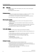
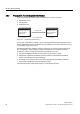
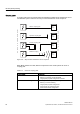
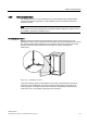
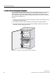
Table Of Contents
- Titel
- SIMATIC Sensors RFID systems SIMATIC RF300
- Legal Information
- Table of contents
- 1 Introduction
- 2 Safety information
- 3 System overview
- 4 RF300 system planning
- 4.1 Fundamentals of application planning
- 4.1.1 Selection criteria for SIMATIC RF300 components
- 4.1.2 Transmission window and read/write distance
- 4.1.3 Width of the transmission window
- 4.1.4 Impact of secondary fields
- 4.1.5 Permissible directions of motion of the transponder
- 4.1.6 Operation in static and dynamic mode
- 4.1.7 Dwell time of the transponder
- 4.1.8 Communication between communication module, reader (with IQ-Sense interface) and transponder
- 4.1.9 Calculation example (IQ-Sense)
- 4.1.10 Communication between communication module, reader (with RS422 interface) and transponder
- 4.1.11 Calculation example (RS422)
- 4.2 Field data for transponders, readers and antennas
- 4.3 Relationship between the volume of data and the transponder speed
- 4.4 Installation guidelines
- 4.5 Chemical resistance of the transponders
- 4.6 EMC Directives
- 4.1 Fundamentals of application planning
- 5 Readers
- 5.1 Overview
- 5.2 RF310R with IQ-Sense interface
- 5.2.1 Features
- 5.2.2 Pin assignment of RF310R IQ-Sense interface
- 5.2.3 Display elements of the RF310R reader with IQ-Sense interface
- 5.2.4 Ensuring reliable data exchange
- 5.2.5 Metal-free area
- 5.2.6 Minimum distance between RF310R readers
- 5.2.7 Technical data for RF310R reader with IQ-Sense interface
- 5.2.8 FCC information
- 5.2.9 Ordering data of RF310R with IQ-Sense interface
- 5.2.10 Dimension drawing

RF300 system planning
4.6 EMC Directives
SIMATIC RF300
80 System Manual, 09/2007, J31069 D0166-U001-A5-7618
Prevention of interference by optimum configuration
Good interference suppression can be achieved by installing SIMATIC PLCs on conducting
mounting plates (unpainted). When setting up the control cabinet, interference can be
prevented easily by observing certain guidelines. Power components (transformers, drive
units, load power supply units) should be arranged separately from the control components
(relay control unit, SIMATIC S7).
As a rule:
● The effect of the interference decreases as the distance between the interference source
and interference sink increases.
● The interference can be further decreased by installing grounded shielding plates.
● The load connections and power cables should be installed separately from the signal
cables with a minimum clearance of 10 cm.
3RZHUVXSSO\
&&(8
'ULYH
6KLHOG
SODWH
Figure 4-31 Prevention of interference by optimum configuration