
User's Manual Part 1
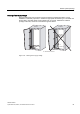
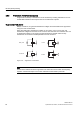
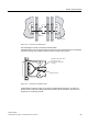

Table Of Contents
- Titel
- SIMATIC Sensors RFID systems SIMATIC RF300
- Legal Information
- Table of contents
- 1 Introduction
- 2 Safety information
- 3 System overview
- 4 RF300 system planning
- 4.1 Fundamentals of application planning
- 4.1.1 Selection criteria for SIMATIC RF300 components
- 4.1.2 Transmission window and read/write distance
- 4.1.3 Width of the transmission window
- 4.1.4 Impact of secondary fields
- 4.1.5 Permissible directions of motion of the transponder
- 4.1.6 Operation in static and dynamic mode
- 4.1.7 Dwell time of the transponder
- 4.1.8 Communication between communication module, reader (with IQ-Sense interface) and transponder
- 4.1.9 Calculation example (IQ-Sense)
- 4.1.10 Communication between communication module, reader (with RS422 interface) and transponder
- 4.1.11 Calculation example (RS422)
- 4.2 Field data for transponders, readers and antennas
- 4.3 Relationship between the volume of data and the transponder speed
- 4.4 Installation guidelines
- 4.5 Chemical resistance of the transponders
- 4.6 EMC Directives
- 4.1 Fundamentals of application planning
- 5 Readers
- 5.1 Overview
- 5.2 RF310R with IQ-Sense interface
- 5.2.1 Features
- 5.2.2 Pin assignment of RF310R IQ-Sense interface
- 5.2.3 Display elements of the RF310R reader with IQ-Sense interface
- 5.2.4 Ensuring reliable data exchange
- 5.2.5 Metal-free area
- 5.2.6 Minimum distance between RF310R readers
- 5.2.7 Technical data for RF310R reader with IQ-Sense interface
- 5.2.8 FCC information
- 5.2.9 Ordering data of RF310R with IQ-Sense interface
- 5.2.10 Dimension drawing

RF300 system planning
4.6 EMC Directives
SIMATIC RF300
82 System Manual, 09/2007, J31069 D0166-U001-A5-7618
4.6.6 Prevention of interference sources
A high level of immunity to interference can be achieved by avoiding interference sources.
All switched inductances are frequent sources of interference in plants.
Suppression of inductance
Relays, contactors, etc. generate interference voltages and must therefore be suppressed
using one of the circuits below.
Even with small relays, interference voltages of up to 800 V occur on 24 V coils, and
interference voltages of several kV occur on 230 V coils when the coil is switched. The use
of freewheeling diodes or RC circuits prevents interference voltages and thus stray
interference on conductors installed parallel to the coil conductor.
9DOYHV
%UDNHV
5HOD\FRLOV
&RQWDFWRUV
Figure 4-33 Suppression of inductance
Note
All coils in the cabinet should be suppressed. The valves and motor brakes are frequently
forgotten. Fluorescent lamps in the control cabinet should be tested in particular.