
User's Manual Part 1
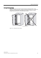
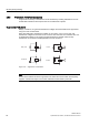
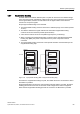
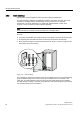
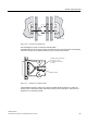

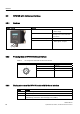
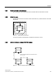
Table Of Contents
- Titel
- SIMATIC Sensors RFID systems SIMATIC RF300
- Legal Information
- Table of contents
- 1 Introduction
- 2 Safety information
- 3 System overview
- 4 RF300 system planning
- 4.1 Fundamentals of application planning
- 4.1.1 Selection criteria for SIMATIC RF300 components
- 4.1.2 Transmission window and read/write distance
- 4.1.3 Width of the transmission window
- 4.1.4 Impact of secondary fields
- 4.1.5 Permissible directions of motion of the transponder
- 4.1.6 Operation in static and dynamic mode
- 4.1.7 Dwell time of the transponder
- 4.1.8 Communication between communication module, reader (with IQ-Sense interface) and transponder
- 4.1.9 Calculation example (IQ-Sense)
- 4.1.10 Communication between communication module, reader (with RS422 interface) and transponder
- 4.1.11 Calculation example (RS422)
- 4.2 Field data for transponders, readers and antennas
- 4.3 Relationship between the volume of data and the transponder speed
- 4.4 Installation guidelines
- 4.5 Chemical resistance of the transponders
- 4.6 EMC Directives
- 4.1 Fundamentals of application planning
- 5 Readers
- 5.1 Overview
- 5.2 RF310R with IQ-Sense interface
- 5.2.1 Features
- 5.2.2 Pin assignment of RF310R IQ-Sense interface
- 5.2.3 Display elements of the RF310R reader with IQ-Sense interface
- 5.2.4 Ensuring reliable data exchange
- 5.2.5 Metal-free area
- 5.2.6 Minimum distance between RF310R readers
- 5.2.7 Technical data for RF310R reader with IQ-Sense interface
- 5.2.8 FCC information
- 5.2.9 Ordering data of RF310R with IQ-Sense interface
- 5.2.10 Dimension drawing

Readers
5.2 RF310R with IQ-Sense interface
SIMATIC RF300
System Manual, 09/2007, J31069 D0166-U001-A5-7618
89
5.2.4 Ensuring reliable data exchange
The "center point" of the transponder must be situated within the transmission window.
5.2.5 Metal-free area
The RF310R can be flush-mounted in metal. Please allow for a possible reduction in the field
data values.
D
D
DD
6,0$7,&
5)5
Figure 5-1 Metal-free area for RF310R
To avoid any impact on the field data, the distance a should be ≥ 20 mm.
5.2.6 Minimum distance between RF310R readers
ุPP
0LQLPXPGLVWDQFHEHWZHHQ5)5DQG5)5
'
'
'
5)5
6,0$7,&
5)5
6,0$7,&
5)5
6,0$7,&
Figure 5-2 Minimum distance between RF310R readers