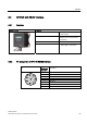
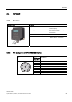
Readers 5.3 RF310R with RS422 interface 5.3 RF310R with RS422 interface 5.3.1 Features Reader RF310R Features Structure ① RS422 interface Field of application Identification tasks on small assembly lines in harsh industrial environments Read/write distance to transponder Max. 30 mm Data transmission rate • • ② Status display 5.3.2 Read: approx. 3100 byte/s Write: approx.
Readers 5.3 RF310R with RS422 interface 5.3.3 Display elements of the RF310R reader with RS422 interface Color Meaning Green Operating voltage present, reader not initialized or antenna switched off Permanentl y on Operating voltage present, reader initialized and antenna switched on Yellow1) Transponder present Flashing red Error has occurred, the type of flashing corresponds to the error code in the table in Section "Error codes".
Readers 5.3 RF310R with RS422 interface 5.3.
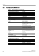
Readers 5.3 RF310R with RS422 interface 5.3.7 Technical specifications of the RF310R reader with RS422 interface Table 5-3 96 Technical specifications of the RF310R reader with RS422 interface Inductive interface to the transponder Transmission frequency for power/data 13.56 MHz Antenna Integrated Interface to communication module RS422 (3964R protocol) Baud rate 19200 baud, 57600 baud, 115200 baud Cable length between reader and communication module Data cable length max.
Readers 5.3 RF310R with RS422 interface 5.3.8 FCC information Siemens SIMATIC RF310R with RS422 interface FCC ID: NXW-RF310R This device complies with Part 15 of the FCC rules. Operation is subject to the following two conditions: (1) This device may not cause harmful interference. (2) This device must accept any interference received, including interference that may cause undesired operation.
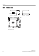
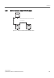
Readers 5.3 RF310R with RS422 interface Dimension drawing 5.3.
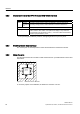
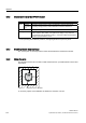
Readers 5.4 RF340R 5.4 RF340R 5.4.1 Features Reader RF340R Features Design ① RS422 interface Area of application Identification tasks on assembly lines in harsh industrial environments Read/write distance to transponder max. 60 mm Data transmission rate • • ② Status display 5.4.2 Read: approx. 3,100 byte/s Write: approx.
Readers 5.4 RF340R 5.4.3 Display elements of the RF340R reader Color Meaning Green Operating voltage present, reader not initialized or antenna switched off Permanentl y on Operating voltage present, reader initialized and antenna switched on Yellow1) Transponder present Flashing red Error has occurred, the type of flashing corresponds to the error code in the table in Section "Error codes".
Readers 5.4 RF340R 5.4.
Readers 5.4 RF340R 5.4.7 Technical data of the RF340R reader Table 5-4 102 Technical specifications of the RF340R reader Inductive interface to the transponder Transmission frequency for power/data 13.56 MHz Antenna Integrated Interface to communication module RS422 (3964R protocol) Baud rate 19200 baud, 57600 baud, 115200 baud Cable length between reader and communication module Data cable length max.
Readers 5.4 RF340R 5.4.8 FCC information Siemens SIMATIC RF340R FCC ID: NXW-RF340R This device complies with Part 15 of the FCC rules. Operation is subject to the following two conditions: (1) This device may not cause harmful interference. (2) This device must accept any interference received, including interference that may cause undesired operation.
Readers 5.4 RF340R Dimension drawing 5.4.
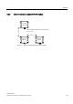
Readers 5.5 RF350R 5.5 RF350R 5.5.1 Features Reader RF350R Features Design ① Antenna connection ② RS422 interface ③ Status display 5.5.2 Area of application Identification tasks in assembly lines in harsh industrial environments; for external antennas (ANT 1, ANT 18, ANT 30) Read/write distance to transponder Max. 60 mm Data transmission rate • • Read: approx. 3,100 byte/s Write: approx.
Readers 5.5 RF350R 5.5.3 Display elements of the RF350R reader Color Green Operating voltage present, reader not initialized or antenna switched off Permanentl y on Operating voltage present, reader initialized and antenna switched on Yellow1) Transponder present Flashing red Error has occurred, the type of flashing corresponds to the error code in the table in Section "Error codes".
Readers 5.5 RF350R 5.5.6 Technical data of the RF350R reader Table 5-5 Technical specifications of the RF350R reader Inductive interface to the transponder Transmission frequency for power/data 13.56 MHz Antenna External, plug-in MOBY E antennas ANT 1, ANT 18 or ANT 30 Interface to communication module RS422 (3964R protocol) Baud rate 19200 baud, 57600 baud, 115 baud Cable length between reader and communication module Data cable length max.
Readers 5.5 RF350R 5.5.7 FCC information Siemens SIMATIC RF350R FCC ID: NXW-RF350R This device complies with Part 15 of the FCC rules. Operation is subject to the following two conditions: (1) This device may not cause harmful interference. (2) This device must accept any interference received, including interference that may cause undesired operation.
Readers 5.5 RF350R Dimension drawing 5.5.
Readers 5.5 RF350R 5.5.10 Antennas 5.5.10.
Readers 5.5 RF350R ANT 30 The ANT 30 is designed for use in small assembly lines. In comparison to ANT 18, the maximum write/read distance is approximately 60 % larger. Due to its compact construction, the antenna can be easily positioned for any application using two plastic nuts (included in the package). The antenna cable can be connected at the reader end. With the RF320T, RF340T and RF350T tags, communication with the data storage unit is only possible in static mode.
Readers 5.5 RF350R 5.5.10.2 Ensuring reliable data exchange The "center point" of the transponder must be situated within the transmission window. 5.5.10.3 Metal-free area The antennas ANT1, ANT18 and ANT30 can be flush-mounted on metal. Please allow for a possible reduction in the field data values.
Readers 5.
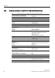
Readers 5.5 RF350R 5.5.10.4 Minimum distance between antennas 'D $17 $17 'E B PP 'D ! B PP 'E ! $17 Figure 5-14 'D 7KH UHDGHU HOHFWURQLFV FDQ EH PRXQWHG GLUHFWO\ DORQJVLGH HDFK RWKHU Minimum distance for ANT 1 'D 'D ุ PP Figure 5-15 114 Minimum distance for ANT 18 SIMATIC RF300 System Manual, 09/2007, J31069 D0166-U001-A5-7618
Readers 5.
Readers 5.5 RF350R 5.5.10.5 Technical data for antennas Table 5-6 Technical data for antennas ANT1, ANT18 and ANT30 Antenna ANT1 ANT18 ANT30 Read/write distance antenna to transponder (Sg) max 100 mm 15 mm 24 mm Enclosure dimensions in mm 75 x 75 x 20 (L x W x H) M18 x 1.0 x 55 (Ø x thread x L) M30 x 1.
Readers 5.5 RF350R Dimension drawings for antennas 5.5.10.
Readers 5.6 RF380R 5.6 RF380R 5.6.1 Features Reader RF350R Features Structure ① RS232 or RS422 interface Field of application Identification tasks on assembly lines in harsh industrial environments Read/write distance to transponder Max. 150 mm Data transmission rate • • ② Status display 5.6.2 Read: approx. 3,100 byte/s Write: approx.
Readers 5.6 RF380R 5.6.3 Display elements of the RF380R reader Color Green Operating voltage present, reader not initialized or antenna switched off Permanentl y on Operating voltage present, reader initialized and antenna switched on Yellow1) Transponder present Flashing red Error has occurred, the type of flashing corresponds to the error code in the table in Section "Error codes".
Readers 5.6 RF380R 5.6.
Readers 5.6 RF380R 5.6.7 Technical specifications of the RF380R reader Table 5-7 Technical specifications of the RF380R reader Inductive interface to the transponder Transmission frequency for power/data 13.56 MHz Antenna integrated Interface to communication module RS232 or RS422 (3964R protocol) Baud rate 19200 baud, 57600 baud, 115200 baud Cable length between reader and communication module RS422 data cable length: max. 100 m RS232 data cable length: Max.
Readers 5.6 RF380R 5.6.8 FCC information Siemens SIMATIC RF380R FCC approval pending Caution Any changes or modifications not expressly approved by the party responsible for compliance could void the user's authority to operate the equipment. Order No. Reader RF380R With RS422 interface (3964R) IP67; -10 °C to +60 C, dimensions 160 x 96 x 40 (L x W x H in mm); with integrated antenna; max. limit distance 150 mm (depending on transponder) 6GT2801-3AA10 Dimension drawing 5.6.
Transponders 6.1 6 Overview Transponders consist predominantly of logic, FRAM and/or EEPROM. If a transponder moves into the transmission window of the reader, the necessary power for all of the circuit components is generated and monitored by the power supply unit. The pulse-coded information is prepared in such a way that it can be processed further as pure digital signals. The handling of data, including check routines, is performed by the logic, which also manages the various memories.
Transponders 6.2 RF320T 6.2 RF320T 6.2.
Transponders 6.2 RF320T 6.2.2 Metal-free area Mounting of RF320T on metal Direct mounting of the RF320T on metal is not allowed. The following figures show the minimum distance between the RF320T and metal: K ! PP 'DWD PHPRU\ 0HWDO 1RQ PHWDO Figure 6-1 Mounting of an RF320T on metal with spacer Flush-mounting of RF320T in metal 0HWDO K ! PP 'DWD PHPRU\ 1RQ PHWDO D ! PP Figure 6-2 Flush-mounting of RF320T in metal with spacer At lower values, the field data change significantly, result
Transponders 6.2 RF320T 6.2.3 Technical data Table 6-1 Technical data for RF320T Memory size 20 bytes EEPROM (r/w), 4 bytes UID (ro) Memory organization Byte-oriented access, write protection possible in 4-byte blocks MTBF (Mean Time Between Failures) in years 1871 Read cycles Unlimited Write cycles, min.
Transponders 6.2 RF320T 6.2.
Transponders 6.3 RF340T 6.3 RF340T 6.3.1 Features Transponder RF340T Features Field of application Memory Identification tasks on small assembly lines in harsh industrial environments Read-only area (4 bytes UID) Read/write memory (8 KB) OTP 1) memory (20 bytes) 1) OTP: 128 Read/write range See Section Field data for transponders, readers and antennas (Page 37) Mounting on metal Direct mounting on metal is possible.
Transponders 6.3 RF340T 6.3.2 Metal-free area Direct mounting of the RF340T on metal is permitted. Mounting of RF340T on metal 0HWDO Figure 6-4 Mounting of RF340T on metal Flush-mounting of RF340T in metal: D D 0HWDO Figure 6-5 Flush-mounting of RF340T in metal The standard value for a is ≥ 20 mm. At lower values, the field data change significantly, resulting in a reduction in the range.
Transponders 6.3 RF340T 6.3.
Transponders 6.3 RF340T 6.3.
Transponders 6.4 RF350T 6.4 RF350T 6.4.1 Features Transponder RF350T Features Field of application Memory Identification tasks on small assembly lines in harsh industrial environments Read-only area (4 bytes UID) Read/write memory (32 KB) OTP 1) memory (20 bytes) 1) OTP: 132 Read/write range See Section Field data for transponders, readers and antennas (Page 37) Mounting on metal Direct mounting on metal is possible.
Transponders 6.4 RF350T 6.4.2 Metal-free area Direct mounting of the RF350T on metal is permitted. Mounting of RF350T on metal Figure 6-7 Mounting of RF350T on metal Flush-mounting of RF350T in metal: Figure 6-8 RF350T flush-mounted in metal The standard value for a is ≥ 20 mm. At lower values, the field data change significantly, resulting in a reduction in the range.
Transponders 6.4 RF350T 6.4.
Transponders 6.4 RF350T 6.4.
Transponders 6.5 RF360T 6.5 RF360T 6.5.
Transponders 6.5 RF360T 6.5.2 Metal-free area Direct mounting of the RF360T on metal is not allowed. A distance ≥ 20 mm is recommended. This can be achieved using the spacer 6GT2190-0AA00 in combination with the fixing pocket 6GT2190-0AB00. Mounting of RF360T on metal 'DWD VWRUDJH XQLW 0HWDO 1RQ PHWDO K Figure 6-10 Mounting of RF360T with spacer The standard value for h is ≥ 20 mm.
Transponders 6.5 RF360T Dimensions of spacer and fixing pocket for RF360T 'LPHQVLRQ VNHWFK )L[LQJ SRFNHW *7 $% 6SDFHU *7 $$ (DUV +ROGLQJ NQREV +ROGLQJ FOLS 0DWHULDO 3$ 7KH VSDFHU FDQ EH GLUHFWO\ PRXQWHG RQ PHWDO ,Q FRPELQDWLRQ ZLWK WKH IL[LQJ SRFNHW D QRQ PHWDO GLVWDQFH RI PP UHVXOWV EHWZHHQ WKH WUDQVSRQGHU DQG PHWDO 0RXQWLQJ :LWK RU VFUHZV 0 :LWK UXEEHUV RQ WKH KROGLQJ FOLSV H J RQ PHVK ER[HV
Transponders 6.5 RF360T 6.5.
Transponders 6.5 RF360T 6.5.
Transponders 6.6 RF370T 6.6 RF370T 6.6.1 Features The SIMATIC RF370T transponder is a passive (i.e. battery-free) data carrier in a square type of construction. SIMATIC RF370T transponder Features Area of application Identification tasks on assembly lines in harsh industrial environments, suitable for larger ranges, e.g.
Transponders 6.6 RF370T 6.6.2 Metal-free area Direct mounting of the RF370T on metal is permitted. Mounting of RF370T on metal Figure 6-14 Mounting of RF370T on metal Flush-mounting of RF370T in metal: D D Figure 6-15 RF370T flush-mounted in metal The standard value for a is ≥ 20 mm. At lower values, the field data change significantly, resulting in a reduction in the range.
Transponders 6.6 RF370T 6.6.3 Mounting instructions It is essential that you observe the instructions in the Section Installation guidelines (Page 54). Properties Description Type of installation Screw fixing (two M5 screws) Tightening torque < 1.
Transponders 6.6 RF370T 6.6.4 Technical specifications 6.6.4.
Transponders 6.6 RF370T 6.6.4.
Transponders 6.6 RF370T 6.6.
Transponders 6.6 RF370T Dimensional drawing 6.6.
Transponders 6.7 RF380T 6.7 RF380T 6.7.1 Features The SIMATIC RF380T transponder is an extremely rugged and heat-resistant round data carrier suitable e.g. for applications in the automotive industry. SIMATIC RF380T transponder Features Area of application Identification tasks in applications (e.g.
Transponders 6.7 RF380T 6.7.2 Installation guidelines for RF380T It is essential that you observe the instructions in the Section Installation guidelines (Page 54). The following section only deals with features specific to the SIMATIC RF380T. 6.7.2.1 Mounting instructions CAUTION You are strongly recommended to only use the tag with the original holder specified. Only this holder guarantees that the data memory observes the listed values for shock, vibration and temperature.
Transponders 6.7 RF380T Assembly of data memory with support &RYHU RSWLRQDO *7 4% $QWHQQD VLGH RI WDJ Figure 6-17 Assembly of tag with support Scope of supply The support is provided with all mounting parts and a mounting diagram. Mounting screws for securing the support are not included. The mounting screws are of diameter M 10. The minimum length is 25 mm. The optional cover can be used for the long and short versions of the support.