
System Manual


Readers
5.6 SIMATIC RF685R
SIMATIC RF600
System Manual, 06/2019, J31069-D0171-U001-A22-7618
199
i
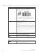
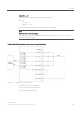
input (DI 0 ... 3)
Ⴠ The inputs are optically isolated through optocouplers.
Ⴠ Level
– Low: 0 ... 7 V
– High: 15 ... 24 V
The following diagrams illustrate various connection possibilities.
Note
M
Minimum time between changes
N
ote that changes on the DI/DQ interface that are not applied for at least 1.5 seconds are
n
ot detected by the reader.
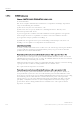
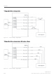
Voltage infeed from internal source (no electrical isolation)
Figure 5-34 Circuit example 1: Digital inputs
Alternative connection possibilities:
Ⴠ Pin 2 (VCC) to Pin 9 DI Common
Ⴠ Pin 1 GND to busbar inputs