
System Manual


System diagnostics
9.1 Diagnostics via the LED displays of the reader
SIMATIC RF600
System Manual, 06/2019, J31069-D0171-U001-A22-7618
471
9
9.1.1 How the LED status display works
Note that the RF610R/RF615R/RF650R readers do not have an LED status display. The
LED status display displays the error messages of the RF680R/RF685R readers.
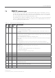
LED status display (ST1 - ST9)
ཱ LED operating display
Figure 9-2 LED displays of the RF680R/RF685R readers
Error messages are indicated by red flashing status LEDs and the red flashing "ER" LED. A
distinction is made between hardware errors (faults) and normal errors. With hardware
errors, the LEDs flash with a fast frequency of 4 Hz. With all other errors, the LEDs flash with
a slow frequency of 2 Hz.
The detailed LED error display described here is enabled as default. If required, you can
disable this in the "Settings - General" menu item of the WBM. If the LED error display is
enabled, a separate LED pattern is assigned to every error in the LED status display. The
displayed LED patterns are based on the error code of the hexadecimal error message
converted to binary.
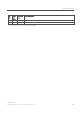
Example
The error "0x12" (XML error message) is displayed. Converted to binary, this results in the
value "0001 0010". This converted value is displayed in the LED status display. The value
"0" means that the corresponding LED does not light up, whereas the value "1" means that
the corresponding LED is lit red. The middle (5th LED) of the LED status display serves as a
"delimiter" and is always lit yellow.
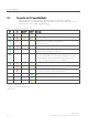
XML error message
h
hexadecimal
Error message
b
binary
LED fault display
0x12 0001 0010