
User Manual


GAMMA instabus
Technical product information
August 2020
Shutter / blind actuator (RL module) RL 521/23 5WG1521-4AB23
AC 230V, 1 x 6A, with detection of end positions
Siemens Switzerland Ltd RS-AG
Building Technologies Division
International Headquarters
Theilerstrasse 1a © Siemens AG 2020 Update: http://www.siemens.com/gamma
CH-6300 Zug Subject to changes
3
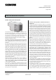
Example of operation
K1
Down
Bus coupling unit
instabus KNX
Shutter / blind actuator RL 521/23
K2
Up
Load circuit
AC 230 V
N PEL1
Up
Down
1
2
6 N
M
1~
Venetian
blind motor
3 L
Detection
of end
position
Channel A
Channel A
K3
Down
K4
Up
Up
Down
4
5
M
1~
Channel B
Channel B
figure 1. Example of operation
Installation notes
• The device is intended for installation in an AP 118
Control Module Box or an AP 641 Room Control Box.
DANGER
• The device must be mounted and commissioned by an
authorized electrician.
• A safety disconnection of the device must be possible.
• The device must not be opened.
• For planning and construction of electric installations,
the relevant guidelines, regulations and standards of the
respective country are to be considered.
• When looping through the L-conductor, take care
that the maximum permissible terminal load current
of 16A is not exceeded!
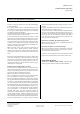
Location / Function of the Display and Operating
Elements
figure 2:
Location / Function of the Display and Operating Ele-
ments
A1 LED for indicating normal operating mode (LED off)
or addressing mode (LED on); returns to normal op-
erating mode automatically after receiving the phys-
ical address
A2 Learning button for switching between normal op-
erating mode and addressing mode and for receiv-
ing the physical address
A3 Bus connection pins of the module for connection
of the bus terminal block for single core conductors
with 0,6...0,8 mm Ø
A4 Type label (with space for physical address of the
actuator)
A5 Terminal Channel A, down
A6 Terminal Channel A, up
A7 Terminal L
A8 Terminal Channel B, down
A9 Terminal Channel B, up
A10 Terminal N
A11 Identification number of the device