
User Manual


GAMMA instabus
Technical product information
August 2020
Shutter / blind actuator (RL module) RL 521/23 5WG1521-4AB23
AC 230V, 1 x 6A, with detection of end positions
Siemens Switzerland Ltd RS-AG
Building Technologies Division
International Headquarters
Theilerstrasse 1a © Siemens AG 2020 Update: http://www.siemens.com/gamma
CH-6300 Zug Subject to changes
5
Installation and wiring
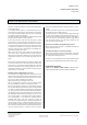
B2 RL module
B3 Type label
B4 Mounting location for RS / RL module in AP 118
Control Module Box (5WG1 118-4AB01) or AP 641
Room Control Box (5WG1 641-3AB01)
B8 Learning button
B9 LED for indicating normal operating or addressing
mode
B10 Bus connection pins for connection of the bus ter-
minal block
B11 Insertion point for bus terminal block
B12 Bus terminal block
B13 Hinge joint for mounting hinge of the RL module
B14 Terminals
• Mounting of an RL module :
- Remove the lid of the AP 118 Control Module Box re-
spectively of the AP 641 Room Control Box.
- AP 641: Remove the SELV (Class 2) cover
- Insert the RL module (B2) into the hinge (B13) of the
mounting location (B4). The terminals (B14) point away
from the insertion point for the bus terminal (B11). The
type label (B3) is on top.
- Swivel the RL module (B2) down until it audibly snaps
into the mounting location (B4).
- Insert the bus terminal (B12) of the mounting location
(B4) onto the bus connection pins (B10) of the RL mod-
ule (B2).
- For assignment of the Physical Address press the learn-
ing button (B8) for a maximum of 2 seconds. The ad-
dressing mode is indicated when the LED is on (B9). It
returns to normal operating mode (LED Off) automati-
cally after receiving the physical address.
- AP641: Insert the SELV (Class 2) cover again.
- Mount the lid again.
figure 3: Mounting of an RL module