s 3 101 Synco™ 200 Universal Controllers RLU2... With programmed standard applications Freely programmable controller, for optimum adaptation to the relevant type of plant P-, PI, or PID mode Menu-driven operation Use For use on basic to complex ventilation, air conditioning and chilled water plant.
Functions Operating modes Selection of operating mode via status inputs: Comfort, Economy, Protection Display of current operating mode (Comfort, Economy, Protection) Setpoints With each sequence controller: Individually adjustable heating and cooling setpoints (or maximum and minimum setpoints) for the Comfort and Economy modes Predefined room temperature setpoint with room unit or setpoint readjuster (passive) With each sequence controller: Predefined setpoint with remote setpoint adjuster (a
Switching and supervisory functions 2-stage frost protection (modulating/ 2-position) or frost protection thermostat (heating sequences delivering 100 % output, fault relay for switching off the fans) (with RLU220 only indication) Control of pumps, constantly ON at low outside temperatures, ON according to load sequence controller (not with RLU220); periodic activation of pump (pump kick) Control of an analog output (not with RLU202).
Ordering When ordering, please give name and type reference of the controller, e.g.: Universal controller RLU236. The products listed under "Accessories" must be ordered as separate items. Equipment combinations For equipment combinations, refer to the Basic Documentation P3101 or to the document covering the selected application.
Mechanical design The universal controller consists of terminal base and controller insert with built-in operation. The terminal base can be fitted to a DIN mounting rail or is screwed directly on a flat surface. It consists of a plastic housing with 2 terminal levels. The controller insert engages in the terminal base. It consists of a plastic housing which accommodates the printed circuit boards. Controller operation is fully integrated.
Mounting and installation notes 3101Z07en Low-voltage side Controllers and extension modules are designed for: Mounting in a standard cabinet to DIN 43 880 Wall mounting on an existing top hat rail (to EN 60715-TH35-7.5) Wall mounting with 2 fixing screws Flush panel mounting with ARG62.201 mounting frame Not permitted are wet or damp spaces.
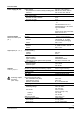
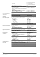
Technical data Power supply (G, G0) Universal inputs Measured value inputs (X...) Rated voltage Requirements for external safety isolating transformer to Frequency Power consumption RLU202, RLU220, RLU222 RLU232, RLU236 Supply line fusing Number Sensors Passive Active Signal sources Passive Active Digital inputs (X..., D...) Outputs Positioning outputs Y... Switching outputs AC 230 V (Q1x...
At 4 A res. 2 x 10⁶ cycles (changeover) 3 x 10⁵ cycles (NO) 1 x 10⁵ cycles (changeover) 0.85 Red. factor at ind. (cos φ = 0.
Materials and colors Terminal base Controller insert Packaging Standards, directives and approvals Environmental compatibility Weight, excl.
Connection diagrams X2 M G1 X3 M X4 M G1 D1 M G0 G N1 Q12 X1 M G0 RLU222 G X2 M G1 G1 X1 M G0 Y1 G0 X2 M G1 Y1 G1 G0 X3 M X4 M G1 G1 Y2 Y2 N2 Q24 D1 M G0 X3 M X4 M G1 G1 Q14 Q23 3101G09 RLU220 Q11 D1 M N1 Q12 G0 Q23 Q11 Q14 N2 Q24 RLU232 G X1 M G0 G1 G X1 M X2 M G1 Y1 G0 X3 M X4 M G1 G1 Y2 G0 X5 M G1 Y3 G0 D1 M D2 M Q11 Q33 Q12 Q14 Q34 RLU236 G0 Legend G1 Y1 G0 G, G0 G1 M G0 X... X..., D... Y... Q...
Connection diagrams Examples: Connections on the measuring side Connection diagram 1: Measuring section with passive main and auxiliary sensors and passive signal source 3101A01 G (3) (1) AC 24 V B M G B1 B M B5 B2 M R5 X... M X... M X... M G0 N1 G0 Connection diagram 2: Measuring section with active sensor and active signal source AC 24 V B M G B3 X... M G1 G (1) (2) (3) (4) GL GN out in G1 M 3101A02 G R2 X...
Preprogrammed standard applications The plant diagrams / connection diagrams assigned to the basic types are only examples. Controller- / basic type Application no. / description RLU202 A01 ADA006 LU0 HQ T B2 N.X1 T T E1 B9 T B1 N.Q1 N.Q2 N.X3 N.X4 S5 N.D1 ADA012 LU0 HQ Supply air temperature control with electric air heater battery.
Application no. / description RLU202 A07 AEC002 LU0 HQ Supply air temperature control with hot water heating coil and DX cooler battery. Options: Room temperature cascade control Outside temperature-dependent functions Remote setpoint readjuster Comfort / Protection Mode changeover (time switch) Plant diagram / connection diagram S01 Controller- / basic type B5 T N.X2 Cascade T T B9 M3 N.X3 N.X4 N.X1 N.Q 2 N.Q 1 R5 T B1 M7 S5 N.
Application no. / description RLU202 U07 HZC002 LU0 HQ Plant diagram / connection diagram S01 Controller- / basic type Boiler temperature control (substitute for RCA12.2) Application: Minimum limitation of the boiler return temperature Options: Remote setpoint adjuster (absolute) Comfort / Protection Mode changeover (time switch) Y3 S5 N.Q1 N.Q2 M N.D1 R5 T T N.X2 B7 N.
RLU220 A03 ADA003 LU2 HQ Extract air (room) temperature control with hot water heating coil and frost protection. Options: Minimum and maximum limitation of the supply air temperature Outside temperature-dependent functions Comfort / Protection Mode changeover (time switch) Plant diagram / connection diagram S01 Application no. / description T B2 N.X1 F3 N.X3 T T T B9 B1 N.X4 N.X2 M Y3 S5 N.Y1 RLU220 A04 N.
Application no. / description RLU220 A10 ADC021 LU2 HQ RLU220 A14 RLU220 A15 T B1 N.X2 M N.X4 M Y3 Y4 N.Y1 N.Y2 S5 N.D1 Supply air temperature control with hot water heating coil and chilled water cooling coil. Options: Room temperature cascade control Outside temperature-dependent functions Remote setpoint readjuster Comfort / Protection Mode changeover (time switch) S01 ADC023 LU2 HQ N.X2 Cascade T T B9 B1 N.X3 N.X1 R5 T N.X4 M M Y3 Y4 S5 N.Y1 N.Y2 N.
Application no. / description RLU220 A17 AEAD04 LU2 HQ Supply air temperature control with mixed air dampers, hot water heating coil, frost protection. Options: Room temperature cascade control Outside temperature-dependent functions Comfort / Protection Mode changeover (time switch) Plant diagram / connection diagram S01 Controller- / basic type 1 Y2 M Y1 N.Y2 M F3 Y6 N.X 3 1 T T T B9 B1 N.X4 N.X1 M S5 Y3 N.
Application no. / description RLU220 U06 AZL001 LU2 HQ Plant diagram / connection diagram B25 Differential pressure control of air with speed-controlled fan. Options: Minimum and maximum limitation of the differential pressure Remote setpoint adjuster Comfort / Protection Mode changeover (time switch) N.X2 f1 B24 p N.X1 [Pa] T f2 p S01 Controller- / basic type R5 N.X3 G1 N.Y1 S5 N.D1 RLU220 U07 AZL004 LU2 HQ B25 Differential pressure control of air with speed-controlled fans.
Application no. / description RLU222 A03 ADA014 LU2 HQ Supply air temperature control with hot water heating coil. Options: Room temperature cascade control Outside temperature-dependent functions Remote setpoint readjuster Comfort / Protection Mode changeover (time switch) Plant diagram / connection diagram T T T B9 B1 N.X3 N.X1 N.D1 S01 1 T B2 N.X1 F3 N.X3 1 T T T B9 B1 M3 N.X4 N.X2 N.Q2 M S5 Y3 N.D1 ADA005 LU2 HQ S01 N.
Application no. / description RLU222 A10 ADC010 LU2 HQ RLU222 A13 RLU222 A14 RLU222 A15 RLU222 A16 N.X2 Cascade T T B9 N.X3 M3 M4 N.Q1 N.Q2 R5 T N.X4 B1 N.X1 M M Y3 Y4 S5 N.Y1 N.Y2 N.D1 Extract air (room) temperature control with electric air heater battery and chilled water cooling coil.
RLU222 A17 ADC007 LU2 HQ Extract air (room) temperature control with hot water heating coil, frost protection, DX cooler battery and fan release. Options: Minimum and maximum limitation of the supply air temperature Outside temperature-dependent functions Comfort / Protection Mode changeover (time switch) Plant diagram / connection diagram N.Q1 1 T B2 N.X1 F3 N.X3 1 T T T B9 N.X2 N.Y2 M Y3 M7 S5 N.
Application no. / description RLU222 A24 AECD01 LU2 HQ Y2 T M B2 M Y1 N.Y2 M N.X1 Y6 T T B9 M3 N.X3 M7 N.Q1 N.Q2 S5 N.D1 AECD04 LU2 HQ Supply air temperature control with mixed air dampers, hot water heating coil and DX cooler battery. Options: Room temperature cascade control Outside temperature-dependent functions Remote setpoint readjuster Comfort / Protection Mode changeover (time switch) RLU222 A29 RLU222 U01 N.X2 M Cascade M Y1 N.Y2 M Y6 T T B9 M3 N.X3 M7 N.
Application no. / description RLU222 U02 PB0002 LU2 HQ Plant diagram / connection diagram B23 Differential pressure control of water with speed-controlled pumps. Options: Minimum and maximum pressure limit controller Outside temperature-dependent functions Remote setpoint adjuster Comfort / Protection Mode changeover (time switch) N.X2 N.X1 [bar] N.Q2 N.Q1 f1 B22 p f1 f2 f2 G2 G1 N.Y2 N.Y1 T R5 N.X4 T S5 B9 N.D1 N.
Controller- / basic type Application no. / description RLU222 U08 CZC001 LU2 HQ Plant diagram / connection diagram Temperature control of chilled ceilings. Options: Setpoint compensation depending on humidity Deviation alarm Comfort / Protection Mode changeover (time switch) M4 B16 M Y4 N.Q1 RLU222 U10 HZC001 LU2 HQ Temperature control of mixing heating circuit.
Controller- / basic type Application no. / description RLU222 U14 HZC002 LU2 HQ RLU222 U15 Plant diagram / connection diagram Boiler temperature control (substitute for RCA12.2) Application: Minimum limitation of the boiler return temperature Options: Remote setpoint adjuster (absolute) Comfort / Protection Mode changeover (time switch) Y3 S5 N.Q1 N.Q2 M SA0001 LU2 HQ B6 N.
AEAF01 LU3 HQ RLU232 A05 RLU232 A06 T B10 B2 N.X4 N.X1 F3 N.X3 1 T T T B9 N.X5 B1 M3 Y11 N.X2 N.Q3 N.Y2 S5 M N.D1 Y3 S6 N.Y1 N.D2 AEAF02 LU3 HQ Supply air temperature control with heat recovery, hot water heating coil, frost protection and fan release Options: Room temperature cascade control Outside temperature-dependent functions Anti-icing protection for heat recovery Comfort / Economy changeover Comfort / Protection Mode changeover (time switch) N.Q1 1 B5 N.
AECF03 LU3 HQ RLU232 A11 RLU232 A12 Y11 M3 M4 N.Y2 N.Q1 N.Q3 M M Y3 Y4 N.Y1 N.Y3 B1 T R5 N.X5 N.X1 S5 N.D1 S6 N.D2 N.Q1 1 T T B10 B2 N.X5 N.X1 F3 N.X3 1 T T T B9 B1 M3 Y11 N.X4 N.X2 N.Q3 N.Y2 S5 M M Y3 Y4 N.Y1 N.Y3 N.D1 S6 N.D2 N.Q1 1 T T B5 N.X2 Cascade B10 N.X5 F3 N.X3 1 T T T B9 B1 M3 Y11 N.X4 N.X1 N.Q3 N.Y2 S5 M M Y3 Y4 N.Y1 N.Y3 N.D1 S6 N.
RLU232 A16 RLU232 A17 RLU232 U01 RLU232 U02 T B2 N.X1 F3 N.X4 1 T T B9 N.X5 T T B27 B1 N.X3 N.X2 S5 M M M Y3 Y4 Y10 N.Y2 N.Y3 N.Y1 ADFA01 LU3 HQ N.D1 S6 N.D2 N.Q1 Supply air temperature and extract air (room) humidity control (r.h.) with hot water heating coil, frost protection, spray humidifier, chilled water cooling coil and fan release.
Controller- / basic type Application no. / description RLU232 U03 ZZZ003 LU3 HQ Plant diagram / connection diagram DC 0 ... 10 V X1 M G G1 D1 M Q11 Q33 Q14 Q34 A01 Linear 2-step switch RLU232 Q12 G0 2Q LIN. ZZZ004 LU3 HQ DC 0 ... 10 V Binary 2-step switch G X1 M G1 D1 M Q11 Q33 Q14 Q34 A01 RLU232 U04 RLU232 Q12 G0 Q1 Q1 ZZZ005 LU3 HQ DC 0 ... 10 V Variable 2-step switch X1 M G G1 D1 M Q11 Q33 Q14 Q34 A01 RLU232 U05 2Q BIN. Q2 RLU232 G0 Q12 2Q VAR.
Controller- / basic type Application no. / description RLU236 A05 ADC005 LU3 HQ RLU236 A08 RLU236 A09 RLU236 A10 E1 Y7 N.Q1 N.Q2 N.Q3 N.Q4 N.Y1 S5 M7 S6 N.Q5 N.Q6 ADC013 LU3 HQ Supply air temperature control with electric air heater battery and DX cooler battery.
Controller- / basic type Application no. / description RLU236 A11 AECD02 LU3 HQ RLU236 A14 RLU236 U01 RLU236 U02 M Y2 Y6 M S5 S6 M Y1 B31 E2 E1 N.Q3 N.Q4 N.Q1 N.
Controller- / basic type Application no. / description RLU236 U03 AZL003 LU3 HQ RLU236 U07 RLU236 U08 N.Q2 N.Q3 N.Q4 N.Q5 N.Q6 S5 S6 S01 ADI004 LU3 HQ Extract air (room) humidity control (r.h.) with DX cooler battery.
Controller- / basic type Application no. / description RLU236 U09 ZZZ007 LU3 HQ Plant diagram / connection diagram DC 0 ... 10 V X1 M G1 G Q11 Q23 Q33 Q41 Q53 Q63 Q14 Q24 Q34 Q42 Q44 Q54 Q64 A01 Linear 4-step switch RLU236 G0 Q12 4Q LIN. ZZZ008 LU3 HQ DC 0 ... 10 V Linear 5-step switch G X1 M G1 Q11 Q23 Q33 Q41 Q53 Q63 Q14 Q24 Q34 Q42 Q44 Q54 Q64 A01 RLU236 U10 RLU236 Q12 G0 5Q LIN. ZZZ009 LU3 HQ DC 0 ...
Controller- / basic type Application no. / description RLU236 U15 ZZZ013 LU3 HQ Plant diagram / connection diagram DC 0 ... 10 V X1 M G1 G Q11 Q23 Q33 Q41 Q53 Q63 Q14 Q24 Q34 Q42 Q44 Q54 Q64 A01 Variable 6-step switch RLU236 Q12 G0 6Q VAR. ZZZ014 LU3 HQ DC 0 ... 10 V Binary step switch with 7 steps (3 relays) G X1 M G1 Q11 Q23 Q33 Q41 Q53 Q63 Q14 Q24 Q34 Q42 Q44 Q54 Q64 A01 RLU236 U16 RLU236 G0 Q12 3Q BIN. Q1 Q1 Q1 Q1 ZZZ015 LU3 HQ Q3 Q2 DC 0 ...
Dimensions (dimensions in mm) RLU202, RLU220, RLU222 123 86 5 3 3 90 66,4 = = 97 EN 60 715-TH 35-7.5 3101M02 44 3 = 50 44,5 35 = ø 10,5 ø5 2 3 RLU232, RLU236 86 176 5 3 90 66,4 = EN 60 715-TH 35-7.
ARG62.201 Panel cutout if controller shall be wired prior to mounting: 3101M09 4,4 66,4 45 4,4 L3 L1 L2 7,8 18 3101M08 10,7 18,5 82 66,4 4,4 45 24 Panel cutout if controller shall be wired after mounting: L3 4,4 87 45 24 5,6 199 5,6 143 3101M10 168 3101M11 113 87 Mounting frame for RLU232 and RLU236: 45 Mounting frame for RLU202, RLU220 and RLU222: L1 18 L2 Type L1 L2 RLU202, RLU220, RLU222 97 133 RLU232, RLU236 153 189 Published by: Siemens Switzerland Ltd.