
Data Sheet for Product


11 / 36
Siemens Universal Controllers CE1N3101en
Smart Infrastructure 2021-11-30
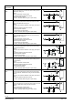
Examples:
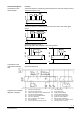
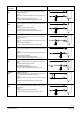
Connection diagram 1: Measuring section with passive main and auxiliary sensors
and passive signal source
G
BM MB MB2
G
G0
X...M MX... MX...
G0
B1 B5 R5
N1
3101A 01
AC 24 V
(1)(3)
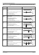
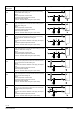
Connection diagram 2: Measuring section with active sensor and active signal
source
G
out
G
G0
MG1 X...
G0
R2
N1
3101A 02
AC 24 V
(3)
GNGL
(2)(1)
X...MG1
B3
BMG in
(4)
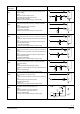
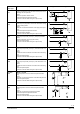
Connection diagrams 3 and 4:
Measuring section with CO2/VOC- and CO2-evaluation
G
G0
U1M
AC 24 V
U2
G
(CO
2
)
B4
G
G0
M X...
N1
G1
(CO
2
/
VOC)
3101A03
G
G
3101A04
G0
N1
G0
U1M
AC 24 V
G
X...M
B4
G1
(CO
2
)
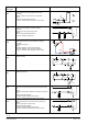
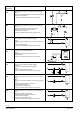
Connection diagram 5:
N1 Universal controller RLU2... K1 Fan release relay
N2 Universal controller RLU222 K2 Pump release relay
B1 Supply air temperature sensor QAM2120.040 R2 Setpoint adjuster BSG61
B3 Frost sensor QAF63.2/QAF63... R5 Setpoint readjuster BSG21.5
B4 CO
2
/VOC sensor QPA2002/2002D S4 On/off switch "Locking signal"
B4 CO
2
sensor QPA2000 S5 Digital time switch SEH62.1
B5 Room temperature sensor QAA24 S7 Manual switch "On/Standby"
F3 Frost unit QAF81... Y Actuating device with 3-position control
H1 Horn for fault status message from fan Y3 Actuating device for heating
Connection diagrams
Connections on the
measuring side
Connections on the
control and monitoring
side
Legend to the connection
diagrams 1 through 5