
Basic Documentation

9.5 Sequence controllers, output assignments
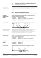
9.5.1 Activating the function block
To activate the CTLOOPx sequence controller, assign a main controlled variable to
it. The necessary settings are described in chapter 0 “Setting up the control
strategy”.
Assign the main
controlled variable
9.5.2 Structure of the sequence controller
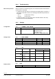
Controller 1 (in RLU222, RLU232 and RLU236) can contain a maximum of 4
sequences in the following combinations:
Conroller 1
RLU222, RLU232,
RLU236
• 1 sequence: Sequence 1 or sequence 4
• 2 sequences: Sequence 1+2, or sequence 1+4, or sequence 4+5
• 3 sequences: Sequence 1+2+4, or sequence 1+4+5
• 4 sequences: Sequence 1+2+4+5
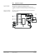
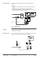
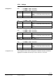
Function diagram The following diagram shows the sequences and their directions of action:
SETHEAT SETCOOL
3140D33en
Heating Cooling
Manipulated variable
Load
Seq 3
Seq 2 Seq 1 Seq 5
Seq 4
The SETHEAT heating setpoint is assigned to successive sequences 1 and 2.
Their output signal acts in the opposite direction to the input variable T.
Explanations relating to
the function diagram
The SETCOOL cooling setpoint is assigned to successive sequences 4 and 5.
Their output signal acts in the same direction as the input variable T.
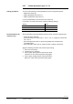
Similar to the above statements, the RLU202 and RLU220 controllers contain a
controller 1 with the following sequences:
RLU202, RLU220
• 1 sequence: Sequence 1 or 4
• 2 sequences: Sequence 1+2, or sequence 1+4, or sequence 4+5
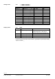
Controller 2 (in RLU222, RLU232 and RLU236 only) can contain a maximum of 2
sequences in the following combinations:
Controller 2
RLU222, RLU232,
RLU236
• 1 sequence: Sequence 1 or 4
• 2 sequences: Sequence 1+4
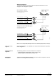
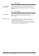
The following diagram shows the sequences and their directions of action:
Function diagram
SET MAX
Seq 1 Seq 4
114 / 174
Siemens Universal Controllers RLU2… CE1P3101en
Building Technologies Controller (CTLOOP x) 29.08.2008