3 133 Synco™ 700 Heating Controller RMH760B • Heating controller of modular design for medium-size or large buildings with own heat source or a district heating connection.
Functions Note Several of the functions listed necessitate extension modules. Refer to page 9 ff.
Boiler temperature control • Control of the boiler temperature with a 1-stage, 2-stage or modulating burner (modulating burner with modulating 3-position or DC 0…10 V control, with checkback signal) • Acquisition of the flue gas temperature, with alarm when limit value is reached • Acquisition of the pump’s flow rate • Maximum and minimum limitation of the boiler temperature • Maintained boiler return temperature controlled via mixing valve (3-position or DC 0…10 V), or bypass pump • Control of a shutoff v
• Holiday functions − Selectable DHW operating mode for holidays − Holiday and special day program with 16 periods per year − Time program for special days • External contact for changeover of operating mode General functions for all control loops Yearly clock Yearly clock with automatic summer- / wintertime changeover. Measuring and signal inputs All measuring and signal inputs are configurable.
Universal inputs of RMH760B can be used as reception objects (in reception zones). • Transmission zones: Universal inputs (N.X1…A9(2).X6) Digital outputs (N.Q1…A9(2).Q4) Analog outputs (N.Y1…A9(2).Y2) • Reception zones: Universal inputs (N.X1…A9(2).X6) Examples for not allowed applications The following applications or input/output values may not be implemented using universal transmission and reception zones: • Safety-relevant plants and equipment (e.g.
Type summary Heating controllers Device Heating controller Selection of languages The following languages are loaded: Type RMH760B-1 Data sheet N3133 English, German, French, Italian, Spanish, Portuguese, Dutch, Danish, Finnish, Norwegian, Swedish, Polish, Czech, Hungarian, Russian, Slovakian, Bulgarian, Greek, Romanian, Slovenian, Serbian, Croatian, Turkish. Note Starting from software version 3.00, all languages are included in the same type.
Technical design Mode of operation The controller is supplied complete with 41 standard types of heating plants ready programmed. Most of them necessitate the use of extension modules. All plant types can be matched to the respective requirements (e.g. configuration as a main controller (district heating connection), configuration of twin pumps, etc.). In addition, an empty application is provided.
DHW heating variants Heating circuit Heating circuit and district heating connection Mixing heating circuit Control of a single pump with supervision of flow and overload Control of a twin pump with supervision of flow and overload Pump heating circuit Pump control Commissioning When commissioning the plant, the relevant plant type is to be entered.
Use of extension modules Extension modules are used when the standard number of inputs and outputs are not sufficient to cover all required functions: Type of extension module Heating circuit module RMZ782B DHW module RMZ783B Universal module RMZ787 Universal module RMZ789 Universal inputs 3 4 4 6 Analog outputs 1 1 – 2 NO 2 3 3 2 Relay outputs Changeover 1 2 1 2 A maximum of 4 extension modules can be used while giving consideration to the following restrictions: • Maximum 2 heating circuit modules R
Engineering notes • The controller can be used in connection with a maximum of 4 extension modules • The controller operates on AC 24 V.
Commissioning notes • The configuration and parameters of the standard applications programmed in the controller can be changed any time on site by personnel trained by Siemens who have the respective access rights to the plant, using the RMZ790 or RMZ791 operator unit or, online or offline, with the help of the service tool • During the commissioning process, the application remains deactivated and the outputs are in a defined off state.
Technical data Power supply (G, G0) Functional data Analog inputs X1…X6 Digital inputs X1…X6 Positioning output Y1, Y2 Switching outputs Q1x…Q5x Rated voltage Requirements for external safety isolating transformer (100 % duty, max. 320 VA) Frequency Power consumption (excl.
Power supply external devices (G1) Voltage Current Interfaces Konnex bus Type of interface Bus loading number Bus power supply (decentral, can be switched off) Power failure of short duration to EN 50 090-2-2 Extension bus Connector specification Number of plugging cycles Service tool connection facility AC 24 V max. 4 A Permissible cable lengths For passive measuring and positioning signals* LG-Ni 1000 0…1000 Ω 1000…1235 Ω Contact sensing For DC 0…10 V measuring and control signals Konnex TP1 2.
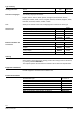
Eco design and labeling directives Controller class Efficiency gain Application with up to three room temperature sensors and one outdoor temperature sensor and modulating control VIII 5.0% Application with one room temperature sensor and one outdoor temperature sensor and modulating control VI 4.0% Application with one outdoor temperature sensor and modulating control II 2.0% Application with up to three room temperature sensors and one outdoor temperature sensor and on/off control VII 3.
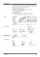
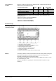
Connection terminals CE+ CE− G, G0 G0 G1 M N1, N2 Q1…, Q4… Q2…, Q3…, Q5… X1…X6 Y1, Y2 Notes Konnex bus data line, positive Konnex bus data line, negative Operating voltage AC 24 V System neutral for signal output Output voltage AC 24 V for powering external active sensors, signal sources and monitors Measuring neutral for signal input Radio interference suppression element for 3-position actuators Potential-free relay outputs (changeover contacts) for AC 24…230 V Potential-free relay outputs (NO contacts
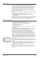
Connection of 3-position actuators N1 Y1 Y2 Heating controller RMH760B 3-position actuator for mixing valve 3-position actuator for shutoff valve F3… F4 K1 K2 Overcurrent release contact Flow switch Motor contactor for pump Motor contactor for pump E1 F1 F2 N1 2-stage burner Limit thermostat Safety limit thermostat Heating controller RMH760B Connection of 1 twin pump or 2 single pumps N1 Heating controller RMH760B Connection of safety loop for a 2-stage burner 16/24 Siemens Building Technologies
Plant types Plant type Description Plant diagram H0–1 N1: DHW circuit with storage tank flow controlled via mixing valve and charging pump, connected directly to uncontrolled header (DHW 2 variant) H0–2 N1: Weather-compensated heating circuit control with mixing valve and circulating pump, connected directly to uncontrolled header H0–3 A3: DHW circuit (DHW 2) N1: Heating circuit N1: Heating circuit A2: Heating circuit A3: DHW circuit (DHW 2) N1: Heating circuit A2: Heating circuit N1:
Plant type Description Plant diagram H1–0 N1: Main controller (district heating connection with heat exchanger), control of the secondary flow temperature with 2-port valve in the primary return, heat supply to internal and external consumers H1–1 N1: Main controller A3: DHW circuit, storage tank charging from heat exchanger controlled via mixing valve, with primary and secondary pump (DHW 4) N1: Main controller A2: Weather-compensated heating circuit control with mixing valve and circulating p
Plant type Description H2–1 H2–2 H2–3 H2–4 Plant diagram N1: Primary controller A3: DHW circuit with storage tank flow controlled via mixing valve, with charging pump (DHW 2) N1: Primary controller A2: Weather-compensated heating circuit control with mixing valve and circulating pump N1: Primary controller A3: DHW circuit (DHW 2) A2: Heating circuit N1: Primary controller A2(1): Heating circuit A2(2): Heating circuit H2–5 N1: Primary controller A3: DHW circuit (DHW 2) A2(1): Heati
Plant type Description H3–2 H3–3 H3–4 Plant diagram N1: Boiler temperature control A2: Weather-compensated heating circuit control with mixing valve and circulating pump N1: Boiler temperature control A3: DHW circuit (DHW 2) A2: Heating circuit N1: Boiler temperature control A2(1): Heating circuit A2(2): Heating circuit H3–5 N1: Boiler temperature control A3: DHW circuit (DHW 2) A2(1): Heating circuit A2(2): Heating circuit H4–0 N1: Boiler temperature control with 1stage burner and
Plant type Description H4–3 H4–4 Plant diagram N1: Boiler temperature control A3: DHW circuit (DHW 2) A2: Heating circuit N1: Boiler temperature control A2(1): Heating circuit A2(2): Heating circuit H4–5 N1: Boiler temperature control A3: DHW circuit (DHW 2) A2(1): Heating circuit A2(2): Heating circuit H5–2 N1: Weather-compensated heating circuit control from heat exchanger connected to uncontrolled header, with 2-port valve in the primary return H5–3 A3: DHW circuit with storage tan
Plant type Description H5–6 N1: Plant diagram Heating circuit A2(1): Heating circuit A2(2): Heating circuit H5–7 A3: DHW circuit (DHW 3) N1: Heating circuit A2(1): Heating circuits A2(2): Heating circuits H6–1 N1: Direct DHW consumption from heat exchanger connected to uncontrolled header, with circulating pump (DHW 6) H6–3 N1: DHW circuit (DHW 6) and weather-compensated heating circuit control from heat exchangers, with 2-port valve in the primary return H6–5 N1: DHW circuit and heating
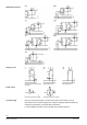
Dimensions Dimensions in mm 23/24 Siemens Building Technologies Heizungsregler RMH760B CE1N3133en 2016-10-22
Issued by Siemens Switzerland Ltd Building Technologies Division International Headquarters Gubelstrasse 22 6301 Zug Switzerland Tel. +41 41-724 24 24 www.siemens.com/buildingtechnologies © Siemens Switzerland Ltd, 2006 Technical specifications and availability subject to change without notice.