s Synco 700 Universal controllers RMU710B, RMU720B, RMU730B Including extension modules RMZ785, RMZ787 and RMZ788 Basic documentation Controller series C CE1P3150en 03.10.
Siemens Switzerland Ltd Infrastructure & Cities Sector Building Technologies Division Gubelstrasse 22 6301 Zug Switzerland Tel. +41 41-724 24 24 www.siemens.com/sbt © 2007 - 2011 Siemens Switzerland Ltd Subject to change 2 / 332 Siemens Building Technologies Universal controllers RMU710B, RMU720B, RMU730B CE1P3150en 03.10.
Table of contents 1 Summary..................................................................................................8 1.1 Product range............................................................................................8 1.2 Synco™ 700 topology...............................................................................9 1.3 Equipment combinations.........................................................................10 1.4 Product documentation .................................
6.7 Room op mode selection (basic types A, U) ...........................................45 6.8 Plant op mode selection (basic types A,P,C,U).......................................46 6.9 Time switch operating modes 6.10 Holidays / special days (basic types A, P, C, U)......................................51 6.11 Room op mode relay (basic types A,P,C,U)............................................54 6.12 Plant operating mode relay (basic types A, P, C, U) ...............................56 6.
11.4 Room or extract air temperature control ...............................................166 11.5 Room or extract air temperature control with supply air limitation........167 11.6 Room supply or extract air cascade control..........................................169 11.7 Cascade / constant control with changeover via casc/const changeover input ......................................................................................................172 11.
17 Frost protection (basic types A and P) .............................................211 17.1 Activate block ........................................................................................211 17.2 Operating principle ................................................................................213 17.3 Acknowledgment...................................................................................216 17.4 Connection diagrams ............................................................
25 Heat demand........................................................................................253 25.1 Activate block (basic types A, P, U).......................................................253 25.2 Activate block (basic type C).................................................................253 25.3 Supervision (basic types A, P, U) ..........................................................254 25.4 Heat demand relay (Q )..................................................................
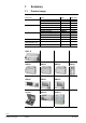
1 Summary 1.1 Product range Room unit Controller Extension modules Operator units Service unit Central communication unit Web server Name Universal controller Universal controller Universal controller Universal module Universal module Universal module Module connector Operator unit, plug-in type Operator unit, detached Bus operator unit Service tool Central communication unit Type RMU710B RMU720B RMU730B RMZ785 RMZ787 RMZ788 RMZ780 RMZ790 RMZ791 RMZ792 OCI700.
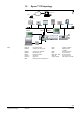
1.2 Synco™ 700 topology Web-Browser Internet Router Ethernet OZW772... RDG.. RXB.. RMZ791 RMZ790 RDF/RDU G..B181.1E/KN RMZ792 RMS.. RMH.. RMK.. RMB.. RMZ78.. OCI700.1 Key RMU7..B RMZ790 Universal controller Operator unit, plug-in type RMH.. RMK.. RMZ791 RMZ792 RMZ78.. OCI700.1 OZW772.. RMS.. Operator unit, detached Bus operator unit Extension modules Service tool Web server Switching and monitoring device RMB.. RXB.. RDG.. RDF.. RDU.. QAW740 G..B181.
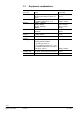
1.3 Equipment combinations Room unit Passive sensors Active sensors Monitors Room units Passive signal sources Active signal sources Actuating devices Volume flow controller VAV Transformer Type All types of sensors using a sensing element LG-Ni 1000, Pt 1000 or T1 (PTC) All sensors operating on AC 24 V modulating output DC 0...10 V QAF81..., QAF64..., QFA81, QFM81, QFX21, QXA2000, QBM81... QAA25, QAA27, QAW740 BSG21.1, BSG21.
1.4 Product documentation In addition to this Basic Documentation, the product documentation listed below provides detailed information on the safe and proper use and operation of Synco™ 700 products in building services plant. Type of document Range description: Synco™700 Basic documentation: Universal controllers RMU710B, RMU720B, RMU730B Data sheet: Universal controller RMU7..
1.5 Performance Function Option modules: Max. 4 connectable, selection from Extension with universal module RMZ785 Extension with universal module RMZ787 Extension with universal module RMZ788 Universal inputs (controller and extension modules): As analog input DC 0...
Function Universal sustained mode in operating mode Precomfort and economy for heating / cooling / humidity or universal Night cooling Frost protection Frost protection unit 2-stage frost protection, air side 2-stage frost protection, water side Preheating function Time switch (ON/OFF) for auxiliary aggregates Logic block for logically linked switching cycles Trend function with 4 inputs to log measured values Meter function to record consumption data for 2 meters (exclusively for display purposes) RMU710B
Example 1.6 Application concept 1.6.1 Programmed application Each universal controller contains 5 tested, preprogrammed applications. The simplest commissioning method is to activate one of the programmed applications. The 5 internally loaded application per controller are described: In this basic documentation in section 31.
1.7 Important notes This symbol draws your attention to special safety notes and warnings. Failure to observe such notes may result in personal injury and / or considerable damage to property. Field of use Synco™ 700 products may only be used for control and supervision of heating, ventilation, air conditioning and chilled water plants. Intended use Prerequisites for flawless and safe operation of Synco™ 700 products are proper transport, installation and commissioning as well as correct operation.
2 Operation Synco™ 700 devices may only be operated by staff who have been instructed by Siemens Building Technologies or their delegates and whose attention has been drawn to potential risks. 2.
2.2 Operation with operator unit 2.2.1 Operator unit functions The operator unit is used to make the settings and readouts required for operation of the controller. All entries made on the operator unit are transmitted to the controller where they are handled and stored; the operator unit itself does not store any data. The information for the user is generated by the controller and passed to the operator unit where it is displayed. 2.2.
Display examples Wednesday 02.04.07 Welcome Information 14:52 Start page Main menu » Setting level: Select setting parameters e.g. on the main menu of the user level Main menu Time switch... Room operating mode… Controller 1… Controller 2… Entry 1 ––.––.–– 25.02 ––.––.–– Start: End: Reason: Delete entry... ––.–– ––.–– Holidays. Main me > Controller 1 Current supply air temp setpoint: 304 Room operating mode 1-6 Preselection: State: Cause: 2.2.
2.2.4 Access rights An access right is defined for each parameter (operating line). There are 3 access levels: Level User level (for the plant operator) Service level (for maintenance) Password level (for commissioning) Access Symbol The user level is always accessible.
3 Philosophy of basic types Four basic types are available for the RMU7..B. They differ by: Field of use Ventilation Primary air handling Chilled water handling Universal Operating mode Switch ON/OFF by room operating mode Demand-dependent by KNX signal Control For room temperature To demand-dependent setpoints by KNX signal By a freely selectable, universal measured value The suitable basic type must be selected for an application.
Auxiliary functions: Indoor air quality control acting on mixed air dampers or fan speed Frost protection Preheating function Sustained mode Night cooling Smoke extraction / Fire alarm off Note The QAW740 room device can be used. 3.2 Basic type P, primary air handling Typical field of use: Demand-dependent control of an air handling plant with VAV individual room control.
Features of individual room control Individual room control functions are described in the documentation P3127 As an option, the following information can be defaulted for individual room control during configuration: Room operating mode with time program. Timer function. Operating mode selector. Holidays and special days. Fire shutdown and smoke extraction. For details, refer to the basic documentation for the RMB795 (P3121). 3.
3.4 Basic type U, universal controller Typical field of use: Control to a flow temperature setpoint (universal measured value). Example: Flow temperature control T T T 3150S10 M Features of basic type U Operating mode: Switch ON/OFF by room operating mode. The plant is switched on and off by its own time switch. The controller operates with room operating modes Comfort, Precomfort, Economy and Protective Mode. Use of Controller 1: By a freely selectable, universal measured value.
4 Commissioning Preparation for use and commissioning of Synco™ 700 controllers must only be undertaken by qualified staff who have been appropriately trained by Siemens Building Technologies. 4.1 Enter commissioning mode During commissioning, both control and plant safety functions remain deactivated! 4.1.1 Introduction during initial power-up The language menu appears the first time power is supplied to the controller. Select the language for commissioning and operating the plant.
4.2 Basic configuration The "Basic configuration" menu is used to make the following settings: Select the basic type or of preprogrammed application Assign extension modules to the controller position First, each device is assigned the basic type or a preprogrammed application. When selecting the plant type, functions are enabled or disabled as required. Configuration Main menu > Commissioning > Basic configuration Operating line Plant type Position 1 Position 2 Position 3 Position 4 4.2.
4.2.3 Troubleshooting If the extension modules and their positions actually used do not agree with the values entered on the controller list, or if an extension modules fails during operation, a fault status message is generated and handling stopped. The outputs maintain the state prior to the fault. Fault status messages No. 7101 7102 7103 7104 4.
4.4 Wiring test A wiring test can be made after all peripheral devices are connected. We recommend to run this test after completing the configuration and settings. Reading values are displayed for the inputs, and aggregates (fans, pumps, etc.) connected to the outputs can be switched on and off.
4.6 Data backup The entire commissioning data set (configuration and all settings) can be saved in the controller after commissioning. If, any time later, an unauthorized person readjusts important values, this function can be used to restore the proper controlled state after commissioning.
4.8 Device information The "Device information" menu provides the following controller information: Display values Example Main menu > Device information > Controller Operating line Comments Plant type Plant type adapted File Device type Software version Hardware version e.g. A01 Standard application or changed standard application e.g. AEFB01 U3B HQ e.g. RMU730B-1 Of the controller Of the controller Meaning: Plant type File Display of the plant type loaded (e.g.
5 General settings 5.1 Time of day and date 5.1.1 Operating principle The controller has a yearly clock with time of day, weekday and date. Time format The following time formats are available: Time format Setting values Presentation Example 24 h Date dd.mm.yyyy (day.month.year) 31.05.2006 hh:mm (hours : minutes) 15:56 am /pm Time of day Date Time of day mm /dd /yy (month / day / year) hh:mm am or pm (hours : minutes am or pm) 05/31/20 06 03:56 PM Main menu > Commissioning > Settings > .
5.1.2 Communication Time of day and date can be exchanged via bus. The controller can be autonomous, slave or master.
5.1.3 Troubleshooting If the clock on the bus is missing and if the local clock is parameterized as the timeof-day slave, operation continues with the internal clock and a fault status message "System time failure" is generated. The clock has a reserve of typically 48 hours for power failure and at least 12 hours. The time of day must be reset if the power outage is longer.
5.2 Select language Every RMU7..B has a number of languages loaded. When switching on the controller for the first time, the "Language" menu appears in English, regardless of the controller’s language set. Select the required language from that menu. The language can also be changed later during operation. The following languages are loaded, depending on the type of controller: Type Language 1 Language 2 Language 3 Language 4 Language 5 RMU7..B-1 German French Italian Spanish Portuguese RMU7..
5.5.2 Setting values File name The file name can be assigned individual text for the selected application: Main menu > Commissioning > Settings > .... or Main menu > Settings > Texts > Operating line File name 5.5.3 Configuration Range Max. 20 characters Factory setting Electronic business card The text for the electronic business card is displayed as an info picture.
6 Operating modes We differentiate between the room operating modes and plant operating modes. Room operating modes refer to the desired climatic conditions in the room and are operated by the end customer. The room operating mode is plant independent. It is used for heating plants, refrigeration plant or for single or 2-speed ventilation plants. The plant is operated in a set plant operating mode to achieve the climatic conditions in the room.
Room operating mode Possible plant operating mode For basic type Economy ( Plant Off: Protective functions ensured Sustained mode (Economy): Demand compensated operation for an unoccupied room; partially suspended plant operation; economy setpoint as switch-on criterion Night cooling: Cooling of a room in summer during vacancy with a lower outside air temperature Plant Off: Protective functions ensured A, P, C, U Protection ( 1) Note on room operating modes ) ): A A, P1) A, P, C, U Nigh
6.2 Effective setpoints as a function of the plant operating mode (basic type A) The setpoints are used as a function of the plant operating mode for control or to switch on or off in sustained mode.
The following table provides an overview of the primary setpoints to switch on/off in dependence of the corresponding plant operating modes: Plant operating mode Controller 1 Controller 2, 3 IAQ controller Sustained mode ( Precomfort) Precomfort cooling setp Precomfort heating setp Precomfort Indoor air quality setpoint Recirculated air mode ( Precomfort) - Upper setpoint Precomfort Lower setpoint Precomfort - Sustained mode ( Economy) Economy cooling setp Economy heating setp Upper setpoint Eco
The following table shows the various possibilities and combinations for 2-speed fans: Plant operating mode Fan control description Normal operation ( Comfort) Permanent for speed 2 as soon as setting parameter "clock priority speed 2" 1) is set to "Yes"; else at least speed 1 is on permanently Normal operation ( Precomfort) Sustained mode ( Precomfort) Recirculated air mode ( Precomfort) Sustained mode ( Economy) Night cooling Plant OFF Changeover criteria: Speed 1, speed 2 Room supply air tempe
6.4 Operating mode block 6.4.1 Room operating mode: Preselection (basic types A, U) The room operating mode for basic types A and U is preset via the schedule's time switch or holiday/special day program or various digital inputs (timer function, switching to selected operating mode, room operating mode selector, holiday input, special day input). In addition, the operating mode can also be set via menu "Room operating mode". 6.4.
6.4.3 Plant operating mode presetting (basic type C) The controller is switched on demand-controlled to demand mode via communication or via the request input at the operating mode block (see section 6.6 "Plant operating mode selection via request input (basic type P, C)"). Here, the plant operating modes "Demand operation" or "Plant OFF" are commanded via communication or request input. In addition, the time switch can be used as an option for other controllers on the bus (see section 6.9.
Recommendation Any digital inputs can be assigned to the inputs. For a better overview, we recommend arranging the inputs side by side. Misconfiguration Misconfiguration has the following effect: Operating line Room operating mode input 1 Room operating mode input 2 6.5.1 Value --N.Xx Effect No effect Timer function The digital input selected for the timer function allows for switching the controller to Comfort mode ( ) for a selected period of time.
6.5.2 Switch to the desired operating mode The digital input enables the plant to be constantly switched to the desired operating mode. Operating line "Preselected room optg mode" is used to select the required operating mode. This operating mode is active until the signal at the control input is no longer present. Only then does the normal 7-day program resume operation.
Application examples Button (restaurant: 2nd speed ventilation) wired to predefined timer function input "N.X...": If the button is pressed for more than 3 s, operating mode Comfort takes effect for the set time (timer function) Window switch connected to predefined room operating mode input 1 "N.X...", preselected room operating mode = Economy: As long as the window remains open, Economy mode is active 6.5.4 Troubleshooting Errors in operation Digital signals cannot be monitored.
6.6.2 Mode of operation: Basic type C If a signal is present at the terminal of the input, it is interpreted as a chilled water request and control becomes active. Setpoint generation is described in section 13, Flow temperature, demand-controlled (basic type C). 6.7 Room op mode selection (basic types A, U) Room operating mode selection for basic types A and U The room operating mode can always be selected with basic types "A" and "U".
6.7.3 Cause (basic types A, U) The various types of user intervention are given as a reason. The following types of user intervention are possible (in order of priority): Room operating mode contact Room optg mode selector (preselected via menu "Room operating mode") Room unit presence button Timer function of the room unit Special day Holidays Time switch 6.8 Plant op mode selection (basic types A,P,C,U) The plant can be switched off via the "Plant operation" menu.
6.8.3 Cause The different functions that can switch the plant On and Off are given as a reason.
6.9 Time switch operating modes , , (basic types A, P, C, U) The controller operates according to the 7-day program entered in the 7-day time switch. Different times from one week to another are not possible. Based on the entered program, the 7-day time switch controls the change of operating modes and the associated setpoints. Operation of the 7-day time switch is described in the operating instructions B3144. 6.9.1 Activate time switch With basic types A and U, the week time switch is always active.
For days without entry, the previous day’s operating mode is assumed and displayed as broken line. The special day ends with the same operating mode it was started with The day following the special day assumes the operating mode of the previous day’s program that would have applied had there been no special day (Tuesday for the following example) Cmf 3131D25 PreCmf Eco 1 Monday Special day Wednesday After all data is entered for a day, it can be copied to other days.
Description The time switch only acts locally on this controller. Time switch has no impact on other controllers on the bus. Master The time switch in this controller is active. The time switch also acts on all other controllers where the local time switch is switched off and that set the geographical zone of this controller as the time switch slave zone. The time switch in this controller is not active.
6.10 Holidays / special days (basic types A, P, C, U) The plant operator can enter days deviating from the normal 7-day program as holidays or special days via the "Holidays / special days". Entry of holidays / special days is described in the operating instructions B3144. With basic types A and U, the holidays / special day program is always active. With basic types P and C, the holidays / special day program is active only if time switch 1 is also active. See section 6.
It is possible to enter if during the holiday period operating mode Protection is to be used. Setting values Main menu > Room operating mode > Main menu > Time switch 1 > Operating line (basic types A, U) (basic types P and C) Range Room operating mode holidays Economy, Economy or Factory setting Protection Economy If the controller is connected to other controllers via communication, the corresponding operating mode applies. 6.10.
6.10.5 Control input "Holidays / special days" The holidays and special days can also be activated via digital inputs. To do this, digital inputs must be assigned. Configuration Main menu > Commissioning > Extra configuration > Operating mode > (A, U) Main menu > Commissioning > Extra configuration > Time switch 1 > (P and C) Operating line Holiday input Special day input Adjustable values / remarks ---, N.X1, N.X2, ... (digital inputs only) ---, N.X1, N.X2, ...
6.11 Room op mode relay (basic types A,P,C,U) 6.11.1 Operating principle The outputs "Operating mode relay 1" and "Operating mode relay 2" on function block operating mode (basic types A and U) or function block Time switch 1 (basic types P and C) allow for outputting the resulting room operating mode to two relay Qx of the controller.
Note on factory setting The factory setting was chosen to allow for direct connection of the digital outputs to the digital inputs of the Synco™200 controller. As the Synco™ 200 controllers do not know operating mode Precomfort, the RMU controller switches the Synco™ 200 controllers directly to Comfort in the event of Precomfort. This setting can be changed to suit individual needs.
6.12 Plant operating mode relay (basic types A, P, C, U) 6.12.1 Operating principle The output "cause" on the operating mode function block allows for the issuing of the plant operating mode via a relay (Section 6.8). Possible application Forwarding of the plant operating mode relay for external processing (e.g. to open skylights or windows as part of active night cooling).
6.12.2 Purpose Setting values Functional check and wiring test During wiring test, the relay outputs can be switched directly allowing for function checks. Main menu > Commissioning > Wiring test > Outputs > Operating line Plant operating mode relay 6.13 Comments Off, On Room control combinations (basic type A) Room control combination means combined control of a room by heating and ventilation controller(s) connected to the same bus. They use the same room operating mode and exchange information.
3150Z03 en Setting for slave ventilation controller QAW740 RM.. RM.. Room operating mode Room operating mode Room unit Ventilation 1 Ventilation 2 Geogr zone = 5 Geogr zone = 5 Geogr zone = 5 Room control comb. = Master Room control comb. = Slave external setpoints The slave ventilation controllers apply the same operating mode as the master within the combination. With regard to setpoints, individual setpoints or the master's setpoints can be applied.
6.13.2 Room control combinations with heating controller 3150Z04en If a heating and a ventilation controller together control the same room, the combination on the ventilation controller must be set to master. QAW740 RM.. RM.. Room operating mode Room operating mode Room unit Ventilation 1 Heating circuit 1 Geogr zone = 5 Geogr zone = 5 Geogr zone = 5 Room control comb. = Master Room control comb.
6.14 Operating mode priorities The following priorities apply to plant operation: 1. ON / OFF during wiring test 2. OFF by fan supervision (flow signal, overload signal); fan release relay signal also is off 3. ON via smoke extraction 4. OFF by one or multiples of the following functions: - Fire alarm off - Fault status messages with plant stop - Supply air fan stop conditions 1 or 2, - Pump fault at simultaneously low outside temperatures 5. Simulation VAV (basic type P) 6.
6.15 Effect of room operating modes (examples) Application example 1 Ventilation with 2-speed fan. Fan speed 2, control to Comfort setpoints Fan speed 1, control to Precomfort setpoints Sustained mode (Economy), night cooling and frost protection active Plant OFF, frost protection active Application example 2 Ventilation with 2-speed fan, speed 2 as per room temperature or IAQ controller.
7 Time switch 2 (ON/OFF) On 2 On / Off Q d Purpose A simple ON/OFF time switch is available e.g. to operate secondary aggregates (e.g. pump) in addition to the main time switch (section 6.9). Time switch 2 has 6 entries per day. 7.1 Activate block and settings Activate time switch 2 via operating line Time switch 2. With Time switch 2, data point "Holiday priority" can be used to select if it can be overridden by the holiday program.
7.2 Communication If the controller is connected to other controllers via the bus, time switch 2 can also be operated as slave (master mode not possible). The following settings are possible: Autonomous time switch 2 Time switch 2 receives the Time switch program from the bus The settings have the following effect: Effect Description Autonomous The time switch only acts locally on this controller Slave The time switch in this controller is not active.
Copy 24-hour profiles After all data is entered for a day, it can be copied to other days. If, for example, Monday is entered, the same profile can be copied to all the other working days (Monday through Friday) and need not be entered again. 7.4 Assign texts Text can be assigned to each time switch and the operation selector. This text appears on the menu and in the operating line. Free text Main menu > Commissioning > Settings > ....
8 Inputs 8.1 Universal inputs Digital signals, passive analog signals or active analog signals can be connected to universal inputs. The following number of universal inputs is available for the individual types of devices: RMU710B: RMU720B: RMU730B: 6 inputs 8 inputs 8 inputs If additional inputs are required, the number of inputs can be increased via extension modules. RMZ785: RMZ787: RMZ788: 8 inputs 4 inputs 4 inputs Max.
The following identifiers are available: Identifier Notes ..Cont.: Identifier Notes Room temperature 1) ppm Outside temperature 1) Universal 000.
8.1.2 Cause The source of the input value is displayed in the value "Cause". The following types are available: Terminal: Used as local terminal LTE mode: Used as LTE transmission and reception objects S-mode: Used as S-mode object Simulation: Input terminal simulation Main menu > Commissioning > Settings > .... or Main menu > Settings > Inputs > ...X...
8.1.4 Troubleshooting Some function blocks require defined inputs; e.g. precommand checkback signal of the motors requires a digital input. During precommand checkback signal configuration only inputs identified as digital are displayed. For this reason, the input identifiers must always be set first during configuration.
8.2 Analog inputs Analog inputs can be activated as described in section 8.1.1 "Activate function". With the analog inputs, the following settings are available: Type, measuring range and readjustment. 8.2.1 Type If the unit is °C, the type can be selected. If the unit is not °C, the type is always 0...10 V. The following types are available: LG-Ni1000 2xLG-Ni1000 T1 Pt1000 0...10 V Setting values Main menu > Commissioning > Settings > .... or Main menu > Settings > Inputs > ...X...
8.2.3 Measured value correction With passive temperature sensors, the measured value can be readjusted by 3.0 to 3.0 K to compensate for line resistance. It is thus possible to on-site calibrate using a reference instrument. Main menu > Commissioning > Settings > .... or Main menu > Settings > Inputs > ...X... Setting values Operating line Correction 8.2.4 Connection examples for sensors Temperature measurement with passive temperature sensor using LG-Ni 1000 sensing element.
G B... B... AC 24 V LG-Ni 1000 B G 3123A07 Connection diagram M LG-Ni 1000 B M M X... G0 N G0 Average temperature measurement with 4 passive sensors using LG-Ni 1000 sensing element. Main menu > Commissioning > Extra configuration > Input identifier > Input configuration Operating line N.X1 Setting °C Main menu > Commissioning > Settings > .... or Main menu > Settings > Inputs > ...X... Setting values Operating line Type Connection diagram G Setting Ni1000 B... B...
8.2.6 Problem and solution Configuration Multiple use of sensors Not all sensor signals can be routed via bus to another device. For this reason, function "Multiple use of sensors" allows for wiring a passive signal at an input terminal directly to a Y-output and provide it as a DC 0…10 V signal. The signal can then be fed to other devices. Main menu > Commissioning > Extra configuration > Sensor multiple use Operating line Signal Y N.
8.3 Special analog inputs The following analog inputs provide advanced, special functions: Supply air temperature Room temperature Extract air temperature Outside temperature Note The additional functionality of identifier "Frost protection", "Frost protection unit 1, 2 and 3", "[Controller 1, 2 and 3] rem setp adj" are described in the sections below. The following table describes the effect of one or several input identifiers connected at the same time.
8.4 Outside temperature 8.4.1 Possible connections The outside temperature can be provided by different sources: Outside temperature connected locally to terminal Outside temperature via bus The following variants are available: Effect Outside temperature at the terminal. Communication outside temperature not active. Controller operates with own outside temperature, no impact on the bus Outside temperature at the terminal. Communication outside temperature active.
Setting values Main menu > Commissioning > Communication > Distribution zones > Operating line Outside temperature zone 8.4.4 Range ----, 1…31 Factory setting ---- Outside temperature simulation To simulate the outside temperature and test the response of the plant, the measured value of the outside temperature can be overridden. Setting values Main menu > Inputs > Operating line Outside temperature simulation Range ----, 50...
8.5 Room temperature 8.5.1 Possible connections The room temperature can only be activated with basic type A. It can be provided by different sources: Room temperature connected locally to the terminal Room temperature via the bus 8.5.2 Averaging, connection variants If communication is active, the room temperature is sent via the bus. The room temperature is sent within the geographical zone and made available to all devices serving the same geographical zone. See section 28.2.
8.5.3 Room temperature at terminal Max one input can be configured for the room temperature. If several inputs are designated as "Room temperature" inputs, only the first of them is used, all others are ignored! Refer to section 8.2 "Analog inputs" for settings and connection diagram for room temperature at the terminal.
8.5.5 Troubleshooting When you exit the Commissioning menu, a check is made to see if room temperature is connected. If the room temperature is connected at this point but is missing later, a message appears. Fault status messages No. 101… Text [N.X1] sensor error 60 Room sensor error plant 1 Effect Non-urgent message; must not be acknowledged Non-urgent message; must not be acknowledged For each system, a maximum of two room temperatures can be sent within the same geographical zone.
8.6 Digital inputs Control function signals can be connected to the digital inputs. See section 8.1.1 "Activate function" on how to activate digital inputs. 8.6.1 Normally closed For each digital input, the normally closed position can be predefined. Main menu > Commissioning > Settings > .... or Main menu > Settings > Inputs > ...X... Setting values Operating line Normally closed 8.6.
8.6.4 Troubleshooting Digital signals cannot be monitored. If important protective functions, such as fire alarm, are connected to this input, it is recommended to a kind of wiring that also triggers a fire alarm when there is no signal (open-circuit) (setting value "Normal position: Closed"). 8.7 Remote setpoint adjuster, absolute The absolute remote setpoint acts on both Comfort and Precomfort setpoints. Suited setpoint adjusters are the QAA25 room operator unit (5...35 °C), the passive BSG21.
8.7.3 Setpoints Comfort The remote setpoint always acts on the lower setpoint (setpoint heating). The dead zone between Seq1+2+3 and Seq4+5 remain the same as for the predefined setpoints. Thus, the current lower Comfort setpoint is = Remote setpoint. And the current upper Comfort setpoint is = Remote setpoint + (Comfort setpoint high – Comfort setpoint low).
8.8 Remote setpoint adjuster, relative The relative remote setpoint acts on both Comfort and Precomfort setpoints. Suitable setpoint adjusters are the QAA27 room operator unit ( 3... 3 K) and the passive BSG21.5 setpoint adjuster ( 3... 3 K). A relative setpoint adjuster is available; it is set assigned to universal controller 1 with the main controlled variable temperature. 8.8.1 Activate function The function is activated by setting the identifier of an input as relative setpoint adjuster.
8.8.4 Connection diagram Connect the setpoint adjuster according to the following diagram: 3144A01 G (3) (1) AC 24 V B M G X... M B1 B M B5 B2 M R5 X... M X... M G0 N1 G0 R5 Passive setpoint shifting unit BSG21.5 8.8.5 Troubleshooting Error in operation When you exit the Commissioning menu, a check is made to see if the setpoint adjuster is connected. If the setpoint adjuster is connected at this point but missing later, message "[...X...] sensor error" appears. Fault status messages No.
8.9 Pulse An input with this identifier can be used to connect a pulse counter. Pulses with the following specification can be received: Mechanical sources (Reed contact) without Namur circuitry, max. pulse frequency of 25 Hz and a min. pulse duration of 20 ms Electronic pulse source with max. pulse frequency of 100 Hz and min. pulse duration of 5 ms 8.9.
Purpose 9 Data acquisition 9.1 Trend 9.1.1 Connections and application The Trend function block is used for time-related recording of measured values. It provides four independent trend channels. A trend channel can record one measured value. Two trend channels can be displayed per Trend view: Primary channel plus extra channel as a reference. It is possible to record signals from local inputs of the controller as well as room temperatures and outside temperature via bus. 9.1.
9.1.3 Settings Trend function settings Main menu > Settings > Data acquisition > Trend > Trend channel 1...4 > Operating line Trend channel 1… Trend channel 4 Trend signal Adjustable values / remarks Channel name (editable text, max.20 characters) Geographical zone (apartment) Assign trend signal: ---, room temperature via bus, outside temperature via bus, N.X1, … A7(2).
9.1.4 Trend signal not available Troubleshooting If a trend signal at the local inputs is no longer available (e.g. due to a faulty sensor), trends are no longer recorded. In this case, observe the messages under: Main menu > Faults > Faults current > If the values are not available via bus, trends are no longer recorded. Power failure or restart After a power failure or when exiting the "Extra configuration" menu (restart controller), the values of the 8-hour and 8-minute views are deleted.
9.2 i i 1 2 Meters Meter Purpose Meters are used to acquire consumption values. Pulses from gas, hot water, cold water and electricity meters are processed. The pulse values represent: Energy in kJ, MJ, GJ, Wh, kWh and MWh Volume in m3, l or ml Variables without unit (0…3 decimal places) Heat cost unit BTU The pulses are converted to consumption values as per the setting values, added, and the cumulated values are stored as 15-month values at midnight upon month rollover.
9.2.3 Pulse valency Every pulse from a pulse source corresponds to a specific consumption value. The pulse valency is printed on the consumption meter. Pulse valency is entered as a numerator and denominator . Example 1 Pulse valency Setting Example 2 Pulse valency Setting Pulse valency 20 liters / pulse Pulse valency numerator = 20 Pulse valency denominator = 1 Pulse unit = liter 3.33..
9.2.6 Display meter readings The current meter reading, the date and the reading of the last 15 months are displayed. Display values Main menu > Data acquisition > Meter 1...2 > Operating line Meter reading current Unit [Readout 1] date [Readout 1] meter reading …. [Readout 15] date [Readout 15] meter reading Comments 0…999'999’999 As per configured display format The monthly values are stored at midnight at the end of the month.
10 Aggregates 10.1 Fan (basic types A and P) The fan block controls and monitors the connected fans.
The fan block and type of fan block are activated by assigning the corresponding outputs to the function block and indicating the required control type. Depending on the type of fan, the following settings must be entered: Configuration example Basic type A Type of fan Type of control Operating line Setting 1-speed 1-speed fan 2-speed 2-speed fan Variable speed Assignment of fixed speeds Speed 1 Speed 2 Speed Pressure sensor Speed 1 Speed 2 Speed Pressure sensor Speed 1 N.Qx ------N.Qx N.
Configuration examples Basic type P Fan type variable Speed Control type Control to constant duct pressure (Measures static pressure) Operating line Step 1 Setting N.Qx Speed N.Yx Pressure sensor N.Xx Control mode Duct pressure (DP stat.) Control to demand-dependent duct pressure (Measures static pressure, damper position signal analog or via KNX bus) Step 1 N.Qx Speed N.Yx Pressure sensor N.Xx Control mode Duct pressure (DP stat.
10.1.2 Example 1-speed fan 1-speed fan, common control of supply and extract air fans, no supervision. 1 a d p x d V x x 1 2 Stop Duct pressure (DP stat) Vol flow (DP dyn) Vol flow (linear 0..10 V) 2 Speed Supply 1 1 Q x x 1 2 Start Q Q Y DO 3150S11en N Q1 Normally, the fan is switched on for the following operating modes: Operating mode Comfort: Precomfort: Economy: Fan On On Off The current state of the fans is displayed on the operator unit.
Normally, the operating modes are assigned to the speeds as follows: Operating mode Fan Speed 2 Speed 1 Off Comfort: Precomfort: Economy: Note the following for 2-speed fans: Both speeds are never active at the same time (disabled in the software) If speed 2 is selected from the start, speed 1 is first switched on for an adjustable period of time (runup time) before switching to speed 2 When switching back from speed 2 to speed 1, the controller switches off speed 2 and switches on speed 1 only aft
10.1.4 Variable-speed fan Assign fixed speeds for 1 or 2-speed operation Rather than relay outputs, the fan speeds for the variable speed drive are output via a 0…10 V signal. Fixed speeds can be assigned to both speeds. At the same time, the IAQ controller is responsible for speed control (see section 16 "IAQ controller (basic types A and P)"). There is a maximum selection.
The current state of the fans is displayed on the operator unit. Main menu > Aggregates > Supply air fan > Display values Operating line Supply air fan Comments Display of the current fan speed: ----, 0...100% Main menu > Aggregates > Extract air fan> Operating line Extract air fan Comments Display of the current fan speed: ----, 0...100% Control to duct pressure (static pressure measurement) DI AI X...
Example 3 The supply air is controlled to prepressure via a VAV controller with supply air fan The extract air fan is controlled to the volumetric flow; the setpoint for the extract air volumetric flow is oriented to the supply air volumetric flow DI y1 y2 y3 V Mod output AA V ? V DO Normally, the operating modes are assigned as follows: Operating mode Comfort: Precomfort: Economy: Fan On On Off If pressure in the ductwork is controlled (e.g.
The corresponding control parameters Xp and Tn as well as the min. speed can be set in addition to the pressure setpoint. Setting values Main menu > Commissioning > Settings > .... or Main menu > Settings > Aggregates > Supply air fan > Main menu > Settings > Aggregates > Extract air fan > Operating line Pressure setpoint Pressure controller Xp Pressure controller Tn Speed min Range Depending on selected input identifier Depending on selected input identifier 00.00...10.00 m:s 0...
Unit: This operating line contains the unit in text form. It is displayed for volumetric flow display values. The numbers are matched to the standard unit m³/s. If another unit is requested (e.g. m³/h), the K-factor must account for this. Speed 1, Speed 2: A two-speed fan allows for controlling to the volumetric flow values for speed 1 and speed 2. Note Case 1 For 1-speed operation, the setpoints for Speed 1 and Speed 2 are the same.
The current state of the fans is displayed on the operator unit. Display values Main menu > Aggregates > Supply air fan > Operating line Supply air fan Actual value volume flow Setpoint volume flow Unit Comments Display of the current fan speed: 0...100% Main menu > Aggregates > Extract air fan > Operating line Extract air fan Actual value volume flow Setpoint volume flow Unit 10.1.5 Comments Display of the current fan speed: 0...
10.1.6 Locking speed 2 at low outside temperatures If the fan is run as a 2-speed fan (via relay or continuous output), the following function is available: Speed 2 can be locked at low outside temperatures. If the outside temperature again exceeds the set value by 2 K, speed 2 is released again. If locking by outside temperature is not desired, set the corresponding value to "---". Setting values Main menu > Commissioning > Settings > ....
If a flow fault occurs at the fan, the plant is shut down. One of the following flow messages appears. Fault status messages No. 1112 Text Supply airflow error 1122 Extract airflow error 10.1.8 Effect Urgent message, with plant stop; must be acknowledged and reset Urgent message, with plant stop; must be acknowledged and reset Overload signal ( ) Here, e.g. overload supervision of a motor protection switch can be connected.
10.1.10 Precommand checkback signal A precommand checkback signal can be configured for each fan block in addition to the precommand. The precommand checkback signal provides information on whether or not the precommand was implemented (e.g. via damper end position switch). Only then is the fan switched on.
10.1.11 Start and stop conditions Two inputs can be configured as stop condition for each fan. In addition, two inputs at which the relevant speed can be selected can be configured as start condition.
10.1.12 Step switch overrun If a step switch with overrun is configured in the same plant, step switch overrun takes priority over the stop condition of the supply air fan. Thus, if the supply air fan is switched off via stop condition, step switch overrun is observed. During operation, step switch overrun acts in the current fan speed and on speed 1 during plant shutdown. 10.1.
10.1.15 Hours run counter The total number of operating hours is acquired for each fan. The counter counts to max. 99 999 hours and then rolls over to 0. Display values Main menu > Aggregates > Supply air fan > Main menu > Aggregates > Extract air fan > Operating line Hours run stage 1 Hours run stage 2 Range 0...99,999 hrs 0...99,999 hrs 10.1.16 Set hours run counter Service staff can set the hours run counter to a defined value or 0. This value can only be changed at the password level.
10.1.18 Wiring test During the wiring test, the fans can be directly switched via the control switch. Wiring test Main menu > Commissioning > Wiring test > Outputs > Operating line Supply air fan Extract air fan Comments Off, On. or Off, Speed 1, Speed 2, or ----, 0...100% Off, On. or Off, Speed 1, Speed 2, or ----, 0...100% 10.1.19 Troubleshooting The fans are switched off if a fault message appears whose cause stops the plant.
10.2 Pump The pump block controls and monitors all pump functions. Single or twin pumps can be controlled. 730 730 720 For each type of universal controller, the following number of pump blocks is available: RMU710B: max. 2 blocks RMU720B: max. 3 blocks RMU730B: max. 4 blocks Explanation of symbols Inputs Precommand checkback signal Precommand (section 10.2.9) (section 10.2.8) Flow signal V Outputs (section 10.2.6) B Pump A, Pump B – Output Pump A, Pump B overload signal A B (section 10.2.
10.2.1 Activate pump block The pump block is activated via assignment to the corresponding outputs. Valid configurations: Motor / Pumps Configuration point Setting Single pump Pump A Pump B Pump A Pump B Qx --Qx Qx Twin pump Any free relay can be assigned to the output. For transparency, we recommend to arrange the relays side by side. Main menu > Commissioning > Extra configuration> Aggregates > Pumps > Pump 1...4 > Configuration Operating line Pump A Pump B 10.2.
10.2.3 Load-dependent by controller The pump can be switched on load-dependent by the controller (see section 15.1.1 "Assign aggregates to sequences"). The controllers can be used for up to three wiring connections; maximum selection applies. The switch-on and switch-off points can be entered via the settings "Loaddependent ON" and "Load-dependent OFF". In normal use, we recommend switching on the pump at 5% load and switching it off at 0% load.
Additional control functions To ensure optimum control of a twin pump, the RMU7..B provides the following control functions in addition to standard functions: Run priority changeover automatic, manual or in the case of pump fault. Adjustable changeover period for orderly changeover of pumps. Run priority changeover Run priority changeover can be automatic, manual, or in the case of fault. Setting value Main menu > Commissioning > Settings > .... or Main menu > Settings > Aggregates > Pump 1...
10.2.5 Delay times A switch-on and switch-off delay can be set for the pumps. These are considered when switching on and off the pump. Example Startcondition On Off DlyOff DlyOn DlyOn DlyOn = DlyOff = Setting values I 3150D10en Pump 0 Switch-on delay Switch-off delay Main menu > Commissioning > Settings > .... or Main menu > Settings > Aggregates > Pump 1...4 Operating line Switch-on delay Switch-off delay Range 00.00...59.59 m:s 00.00...59.59 m:s Factory setting 00.00 m:s 01.
Setting values Main menu > Commissioning > Settings > .... or Main menu > Settings > Aggregates > Pump 1...4 > Operating line Flow delay start Flow delay operation Range 00.00...59.59 m:s 00.00...59.59 m:s Factory setting 02.00 m:s 00.05 m:s The switching values for the flow fault can be set. Setting values Main menu > Commissioning > Settings > .... or Main menu > Settings > Aggregates > Pump 1...
10.2.7 Overload signal (A B ) Here, e.g. overload supervision of a motor protection switch can be connected. Configuration Main menu > Commissioning > Extra configuration > Aggregates > Pumps > Pump 1...4 > Operating line [Pump A] overload [Pump B] overload Adjustable values / remarks ---, N.X1, N.X2, ... (digital inputs only) ---, N.X1, N.X2, ... (digital inputs only) The overload message [Pump A] overload" is sent for 1-speed pumps. For the overload signal, fault acknowledgement can be set.
10.2.8 Precommand For each pump, an associated precommand can be configured. This allows e.g. to open a damper or valve prior to actual pump start as well as shut the damper delayed following pump switch-off. Configuration Main menu > Commissioning > Extra configuration > Aggregates > Pumps > Pump 1...4 > Operating line Precommand Adjustable values / remarks ---, N.Q1, N.Q2, ... (free outputs only) The precommand allows for starting or stopping the pumps either simultaneously or delayed.
Note Function diagram based on single pump Using the precommand checkback signal is sensible only if combined with the configured precommand.
An analog signal can be used as start or stop signal. The limit values for when the corresponding pump is to be switched on or off can be set via setting values "[Start value x] ON" and "[Start value x] OFF". Setting values Main menu > Commissioning > Settings > … or Main menu > Settings > Aggregates > Pump 1...
10.2.13 Behavior in case of pump fault at low outside temperatures If the plant is to be switched off at pump fault and simultaneously low outside temperatures, but continue to run at higher outside temperatures although the related pump is at out of service due to fault, setting parameter "(Fault) plant stop OT <" allows to do just that. Setting values Main menu > Commissioning > Settings > .... or Main menu > Settings > Aggregates > Pump 1...
In a wiring test, the pumps can be switched on or off directly via the control switch. Main menu > Commissioning > Wiring test > Outputs> Wiring test Operating line Pump 1A / Pump 1B Pump 2A / Pump 2B Pump 3A / Pump 3B Pump 4A / Pump 4B Comments Off, On Off, On Off, On Off, On 10.2.16 Priorities The following priorities apply to pump operations: 1. 2. 3. 4. 5. 6. 7. 8. 9. 10. 11. 12.
10.2.18 Operating hours The total number of operating hours is acquired for each pump output. The counter counts to max. 99 999 hours and then rolls over to 0. Display values Main menu > Aggregates > Pump 1…4 > Operating line Operating hours pump A Optg hours pump A Operating hours pump B Optg hours pump B Range 0...99,999 h 0...99,999 h The counter reading can be adapted and e.g. reset to 0 at the password level. Setting values Main menu > Settings > Aggregates > Pump 1...
10.3.2 Inversion of outputs Any output can be inverted. Setting values Main menu > Commissioning > Settings> .... or Main menu > Settings > Aggregates > Modulating output A…D Operating line Inversion Range No, Yes Factory setting No Meaning: Non: 0...100% Load = 0...100% output Yes: 0...100% Load = 100...0% output This means for the sequences: No: hhh _ cc: \\\ _ // Yes: hhh _ cc: /// _ \\ 10.3.3 Limitations The modulating output (Y) can be limited at the top and at the bottom.
10.3.4 Start condition The modulating output can be activated via a digital signal. The output signal is delivered while giving consideration to the limitation. If the start signal is withdrawn, the output delivers 0 V or, in case of inversion, 10 V. A maximum selection is generated. If no start condition is configured, the output is always active. Main menu > Commissioning > Extra configuration > Aggregates > Modulating outputs > Modulating output A...D > Operating line Start condition 10.3.
10.4 Heat recovery equipment (basic types A, P) This function controls the heat recovery equipment. y1 y2 x a a a 1 2 1 2 MECH HR CC.................... Y Q 10.4.1 Activate block To activate the "Heat recovery equipment" function, an output must first be assigned. If a switching output is required, the "Output relay" can be configured on a free relay output.
10.4.3 Maximum Economy changeover (MECH) The purpose of this function is to optimize control of heat recovery in air conditioning systems with regard to operating costs. To activate Maximum Economy Changeover (MECH) of the heat recovery equipment, relevant inputs must be assigned. Configuration Main menu > Commissioning > Extra configuration > Aggregates > Heat recovery equipment > Operating line MECH input 1 Adjustable values / remarks ---, N.X1, N.X2, ...
2. Changeover at an adjustable value Here, an analog input must be assigned to MECH input 1. (Typically: outside temperature or enthalpy difference outside air – extract air). If the adjusted MECH limit value is exceeded, the output is inverted. AI Control by heating sequences (S1, S2, S3) X... OT d a Y OT > MECH limit value Seq. limit.
10.4.4 Monitor efficiency of heat recovery system To activate this function, the relevant two inputs must be assigned. Configuration Main menu > Commissioning > Extra configuration > Aggregates > Heat recovery equipment > Operating line Efficiency measurement input 1 Efficiency measurement input 2 Explanation Adjustable values / remarks ---, N.X1, N.X2, ... , Room temperature, Extract air temperature (only °C, 000.0, 0000) ---, N.X1, N.X2, ... (only °C, 000.
Measuring arrangement supply air T T B2 B5 150 mm T T B9 Bx Xx Yx OT input Note Xx Efficiency 2 Xx N1 Efficiency 1 Due to heat radiation, the distance between sensor BX and the air heating coil LH must be at least 150 mm.
In addition, the following parameters can be set: Setting values Main menu > Commissioning > Settings > .... or Main menu > Settings > Aggregates > Heat recovery equipment > Operating line Fault status message delay Outside temp limit efficiency Correction fan impact Efficiency limit HR efficiency deviation Range 00.00...06.00 h.m 50...150 °C 0.0...5.0 K 0...100% Max. 20 characters of text Factory setting 01.00 h.m 15 °C 0.
Heating and dehumidifying Eh Ex Oa Su 3150D15 Example Without cooling valve setting With cooling valve setting Oa Oa Ex Ex Ccl Ccl Su Su C Hcl cl H cl C cl 3150D16 H cl 3150D17 Hcl Ex Oa Eh Su Extract air Outside air Exhaust air Supply air Hcl Ccl Heating coil Cooling coil The HR output can be inverted. Setting values Main menu > Commissioning > Settings > ....
10.4.7 Function check / wiring test The current state of the heat recovery system is displayed on the operator unit. Display values Main menu > Aggregates > Operating line Output modulating Output relay Efficiency heat recovery Comments 0...100% Off, On ----, 0...100% During the wiring test, the modulating output can be directly controlled. Wiring test Main menu > Commissioning > Wiring test > Outputs > Operating line Heat recovery output 10.4.8 Comments ----, 0...
10.5 Mixed air damper (basic types A, P) This function provides control of an outside air damper with a DC 0...10 V signal. y1 y2 x a a 1 2 TMil Damper MECH CC......... Y 10.5.1 Activate block To activate the "Mixed air damper" function, an output must first be assigned. Configuration Main menu > Commissioning > Extra configuration > Aggregates > Mixed air damper > Operating line Output 10.5.2 Adjustable values / remarks ---, N.Y1, N.Y2, ...
10.5.3 Limitations The modulating output (Y) can be limited at the top and at the bottom. 0...100% output corresponds to the range between "Positioning signal min" (Ymin) and setting value "[Max limitation] end position" (Ymax). Y Function diagram 100 % 10 V Ymax Ymin 0% 0V 100 % 0% Qs Qs = Load demand from the sequence controller "Positioning signal min" (Ymin) is fixed. The upper limit value can be shifted depending on the outside temperature.
10.5.4 Fixed damper setting When the plant is off, the signal is always DC 0 V. If the mixed air damper is not controlled by a controller, "Positioning signal min" is issued at the damper output at switched-on plant and after startup circuit time expiration: 3140D30en Y [%] Function diagram 100 Positioning signal min 0 Plant startup t Plant shutdown If recirculated air operation is active (see section 10.1 "Fan (basic types A and P)"), the outside air damper is closed (DC 0 V).
10.5.6 Priorities The following priorities apply to mixed air temperature control: 1. Startup circuit 2. MECH changeover 3. Mixed air temperature controller signal 4. IAQ controller signal 5. Sequence controller signal 10.5.7 Troubleshooting Errors in operation When you exit the Commissioning menu, a check is made to see if the mixed air temperature sensor is connected. If the sensor is not connected at this point, the "Mixed air temperature control" function is set inactive.
Changeover options There are three changeover options: 1. Changeover triggered externally via a digital signal: Here, a digital input must be assigned to "MECH input 1". The following applies: Normally closed (low outside temperature) = No inversion Operating position (high outside temperature) = Inversion Control by heating sequences (S1, S2, S3) .X... DI Y Digital M M S3 S2 S1 y p y p y p S4 S5 y p y p Operated position T y1 y2 x a a 1 2 TMil Damper MECH AO CC.........
3. Changeover at an adjustable difference between two measured values Here, one analog input each must be assigned to "MECH input 1" and "MECH input 2". (Typically: MECH input 1 = Outside temperature, MECH input 2 = Extract air temperature). The output is inverted if as shown in this example the outside temperature with heating sequence control is greater than the extract air temperature plus MECH limit value. The hysteresis is a set 1 K. .X... AI OT M M Y OT < (EAT + limit value - hysteresis) Seq.
If plant start is triggered by "Smoke extraction" or "Night cooling", there is no startup circuit. On plant startup, the outside air damper operates according to the following diagram: Yx [%] Function diagram 3150D18en 100 Opening of air damper by controller signal Yx min Controller signal... t Plant startup Starting time Normal operation 10 min (fixed) 10.5.11 Function check / wiring test The current state of the mixed air damper is displayed on the operator unit.
Configuration error If the second MECH input does not use the same unit as the first MECH input, only the first input is considered for changeover. If none or only the second input is configured, changeover is deactivated. 10.
10.6.2 The linear step switch connects the relay outputs in equal steps.
Setting values Main menu > Commissioning > Settings > .... or Main menu > Settings > Aggregates > Step switch 1...3 > Operating line Range Factory setting Startup delay Run priority changeover 00.00…10.00 mm:ss No, Yes 00.00 No 10.6.3 Binary step switch The binary step switch is used to switch multistage aggregates. The aggregates must be sized according to the binary load distribution. With the binary step switch, run priority changeover is not possible.
Load distribution applies the following pattern: 3150D24en Y+Q Y 1.Q 1 /16 2.Q 2 /16 3.Q 4 /16 4.
10.6.4 Cascade step switches To increase the number of steps, two or three linear/binary step switches can be interconnected (cascaded).
Linear step switch with 8 steps: SAT SIGNAL Y a N.X1 xY d Seq. limit. Casc/Const Controller 1 With supply air limitation (Ventilation) Cascade Constant (supply air) Cascade/const (alternating) S3 S2 S1 S4 y p y p y p S5 y p y p x y1 y2 y3 y1 y2 y3 Release Step Linear switch 1 Binary Connect 1+2 1 2 3 4 Q Q Q Q Load connection 3150s51en Example 2 Q Q Q Q Y 730 720 Q Q N.Q1 N.Q2 S1 S2 x Release Step Linear switch 2 Binary Connect 2+3 1 2 3 4 Q Q 730 N.
DI 3150S27en Application example X... Digital a p d p Plant x x x x x y1 y2 y3 1 2 Start 1 2 Stop Release Step Linear switch 1 Binary Connect 1+2 1 2 3 4 1 Duct pressure (DP stat) Vol flow (DP dyn) Vol flow (linear 0..10 V) Speed 2 Q Q 1 DO AO d V S upp ly Q x Q Q Q Q Y Y Q... Q... Y... ON OFF load electric air heater battery Y Q fan Overrun checkback t 10.6.7 External release One input can be configured as release for each step switch.
Since measurement variations can occur during operation, a delay time can be set. For example, the following function can be implemented: Release of an electric heating coil via a flow signal. Main menu > Commissioning > Settings > .... or Main menu > Settings > Aggregates > Step switch 1...3 > Operating line Switch-off delay release Range 00.00...10.00 m:s Factory setting 00.
10.6.10 Function check / wiring test The current state of the step switch is displayed on the operator unit. Display values Main menu > Aggregates > Step switch 1…3 > Operating line Step 1 Step 2 Step 3 Step 4 Modulating output Comments Off, On Off, On Off, On Off, On 0...100% During the wiring test, the step switch can be switched directly via the control switch.
10.7 Variable step switch (4…5) This function is used to switch multistage aggregates. All outputs can be set individually. y1 y2 y3 x y1 y2 y3 Release Step switch 4 (var) 1 2 3 4 5 6 Q Q Q Q Q Q 10.7.1 x Release Step switch 5 (var) 1 2 3 4 Y Q Q Q Q Y Activate block The variable step switch is activated by assigning it to output Qx on Step 1 or to a modulating output of output Y. Step switch 4 can be configured for max 6 steps; step switch 5 for max 4 steps.
Setting values Main menu > Commissioning > Settings > .... or Main menu > Settings > Aggregates > Step switch 4…5 > Operating line [Step 1] ON [Step 1] OFF [Step 2] ON [Step 2] OFF [Step 3] ON [Step 3] OFF [Step 4] ON [Step 4] OFF [Step 5] ON [Step 5] OFF [Step 6] ON [Step 6] OFF Range 0...100% 0...100% 0...100% 0...100% 0...100% 0...100% 0...100% 0...100% 0...100% 0...100% 0...100% 0...
DI 3150S27en Application example X... Digital a p d p Plant x x x x x y1 y2 y3 1 2 Start 1 2 Stop Release Step Linear switch 1 Binary Connect 1+2 1 2 3 4 1 Duct pressure (DP stat) Vol flow (DP dyn) Vol flow (linear 0..10 V) Speed 2 Q Q 1 DO AO d V S upp ly Q x Q Q Q Q Y Y Q... Q... Y... ON OFF load electric air heater battery Y Q fan Overrun checkback t 10.7.5 Release external One input can be configured as release for the step switch.
We recommend using the input of the V-belt supervision as a release for the step switch when entering an overrun time for the step switch. This ensures that an electric heating coil is switched on only with flow. Important The external release takes priority over a signal from frost protection or from preheating. In other words, an electric heating coil can be decoupled from the frost function. 10.7.6 Modulating output The output signal of the modulating output (Y) can be limited high and low.
The step switch can be switched directly via the control switch during the wiring test. Wiring test Main menu > Commissioning > Wiring test > Outputs > Operating line Step switch 4 Step switch 5 10.7.9 Comments ---, 0...100% ---, 0...100% Priorities The following priorities apply to the step switch: 1. ON / OFF during wiring test 152/332 Siemens Building Technologies Universal controllers RMU710B, RMU720B, RMU730B Aggregates CE1P3150en 03.10.
10.8 1 2 3 A Logic 1 2 3 A 1 2 B 1 2 B C C 1 2 3 A 1 2 3 A 1 2 B 1 2 B C C Purpose The logic block is used to make logical links to multiple input signals. 4 independent logic function blocks are available. Operation selector One operation selector can be activated per logic block to allow the use to manually intervene at the upper main menu level. Auto, Off and On can be selected. The intervention acts on the output of the logic function block.
The following logic tables show the settable logic functions AND, NAND, OR, NOR, EXOR and EXNOR using the example of 2 inputs. Input 1 0 0 1 1 AND Input 2 0 1 0 1 Input 1 0 0 1 1 OR Input 2 0 1 0 1 Input 1 0 0 1 1 EXOR Input 2 0 1 0 1 Logic tables 10.8.
Important The changeover impacts all time-related parameters of the logic function block (switch-on/off delay and min. switch-on/off time). The time format “h:m“ can be set in 10-minute increments. 10.8.2 Assign texts A specific text can be assigned to each logic and operation selector. This text appears on the menu and in the operating line. Setting values Main menu > Commissioning > Settings > .... or Main menu > Settings > Aggregates > Logic functions > Logic 1...4 > Operating line Logic 1...
10.8.5 Minimum on time For the logic output, a minimum on-time can be set. Thus, when a switch-on command is issued, the output remains active for the time set. Setting values Main menu > Commissioning > Settings > .... or Main menu > Settings > Aggregates > Logic functions > Logic 1...4 > Operating line On time minimum Range 00.00...59.55 m:s Factory setting 00.00 m:s The minimum on-time always takes effect after a switch-on command. 10.8.
10.8.9 Priorities For logic operations, the following priorities apply: 1. 2. 3. 4. 5. 6. 7. On / Off during wiring test Off by "Off time minimum" On by "On time minimum" Off by switch-on delay On by switch-off delay On by operation selector On by logic inputs 10.8.10 Notes If with an analog input of the logic block the switching value On = switching value Off, there is no hysteresis. If an error occurs at a configured input, the "Off" state is issued for the entire logic block.
10.8.11 Application example storage tank charging 3123S05en The following application example shows a solution for a self-holding function. The measured value connected to logic A input 1 gives the switch-on command for storage tank charging. The measured value at logic B input 1 terminates charging.
10.8.12 Application example RS flip-flop N.X2 Digital xY SIGNAL Y N.X1 Digital SIGNAL Y The following application example shows a solution for an RS flip-flop. xY Set Reset x x x x x x x x x x 1 2 3 A 1 2 B 1 2 3 A 1 2 B Logic 1 C Logic 2 C NOR NOR Q d Q Q N.Q1 N.
11 Temperature controller (basic type A) 11.1 General d a Seq. limit.
11.1.3 Priority of functions When simultaneously activating different functions acting on the same controller, the following priority applies: 1. Frost protection 2. Locking of sequences after heating/cooling changeover 3. Preheating function 4. Sequence locking acc to OT 5. Sequence limiter 6. Supply air limiter 7. Sequence controller, assignment of aggregates 11.2 Overview of control modes d a Seq. limit.
Cascade temperature control Control mode Room / supply air temperature cascade control (section 11.6). Extract air / supply air temperature cascade control (section 11.6). Operating line Input identifier N.Xn Input identifier N.Xn Control strategy Casc/const changeover input Input identifier N.Xn Input identifier N.
The following configuration operating lines are used to configure the desired control modes: Configuration Main menu > Commissioning > Extra configuration > Input identifier > Operating line N.X(n) Adjustable values / remarks Activate function by assigning the value to the input: Room temperature, Extract air temperature, Supply air temperature ... RMZ788(2).
Fault status messages When exiting the Commissioning menu, a check is made to see if the room temperature, extract air temperature or supply air temperature are connected. If the corresponding temperature is connected but missing later, a message appears. No. 101… Text [N.
N.X1 SAT Supply air temperature control SIGNAL Y 11.3 xY a d Seq. limit. Casc/Const Controller 1 With supply air limitation (Ventilation) Cascade Constant (supply air) Cascade/const (alternating) S3 S2 S1 y p y p y p 11.3.1 S4 S5 y p y p Operating principle PID control controls the supply air temperature according to the set setpoint. 11.3.2 Supply air setpoints Specific setpoints can be predefined for operating modes and Economy.
Room or extract air temperature control N.X2 RT Extract air temperature control SIGNAL Y Room temperature control N.X1 EAT xY xY a a d Seq. limit. Casc/Const Controller 1 With supply air limitation (Ventilation) Cascade Constant (supply air) Cascade/const (alternating) S3 S2 S1 y p y p y p 11.4.1 SIGNAL Y 11.4 S4 d Seq. limit.
Room or extract air temperature control with supply air limitation N.X1 SAT xY N.X1 EAT xY a S2 S1 y p y p y p 11.5.1 S4 N.X1 SAT xY xY a d Seq. limit. Casc/Const Controller 1 With supply air limitation (Ventilation) Cascade Constant (supply air) Cascade/const (alternating) S3 Extract air temperature control with supply air limitation SIGNAL Y RT SIGNAL Y N.X2 SIGNAL Y Room temperature control with supply air limitation SIGNAL Y 11.5 d Seq. limit.
Display values for room temperature control Display values for extract air temperature control Main menu > Controller 1 > Operating line Actual value room temp Current room temp setpoint Comments Operating line Actual value extract air temp Current setp extract air temp Comments 11.5.3 Setting values Supply air limiter Main menu > Commissioning > Settings > ....
Special case If cooling sequence 4+5 is active, minimum limitation can be lowered by an adjustable value (operating line Reduction min limitation cooling). This allows to prevent the refrigeration machine from switching off immediately in the case of multi-stage cooling. Supply air limitation, relative The set limitation setpoints relate to the temperature differential between the room temperature and the supply air temperature.
Source air opening: Laminar air flow in occupancy area. Supply air may be introduced e.g. max 4 K below the room temperature.
Display values Main menu > Controller 1 > Operating line Actual value room temp Current room temp setpoint Actual value extract air temp Current setp extract air temp Actual value supp air temp Current supply air temp setpoint 11.6.
Cascade / constant control with changeover via casc/const changeover input xY dig xY a N.X1 EAT x Y S3 S2 S1 y p y p y p xY d Seq. limit. Casc/Const Controller 1 With supply air limitation (Ventilation) Cascade Constant (supply air) Cascade/const (alternating) S4 S5 y p y p N.X1 SAT N.X2 dig xY a SIGNAL Y N.X2 Extract air/supply air temperature cascade control (Off for heating, summer) and Supply air temperature control (On for heating, winter) SIGNAL Y N.
11.8 Room control combinations with heating controller If a heating and ventilation controller together control the same room and are connected to the same bus, they can exchange information. Both controllers must have the same geographical zone and both must work with the same room operating mode. 3150Z05en The room control combination (see section 6.13.2) at the ventilation controller must be set to master. QAW740 Room unit Geogr zone = 5 RM.. RM..
11.8.2 Control mode for room or extract air temperature control When the ventilation controller activates "Room temperature control", room influence on the heating controller must be switched off. Also, there may be no thermostatic radiator valves fitted in the room. Both controllers must have the same geographical zone set. Operating principle In the Comfort and Precomfort modes, the ventilation controller ensures that the required room temperature is maintained.
Alternating control strategy SAT xY N.X1 EAT xY a S2 S1 y p y p y p Operating principle SAT xY a d S4 N.X1 xY Seq. limit. Casc/Const Controller 1 With supply air limitation (Ventilation) Cascade Constant (supply air) Cascade/const (alternating) S3 Extract air/supply air temperature cascade control (Off for heating, summer) and Supply air temperature control (On for heating, winter) SIGNAL Y RT N.X1 SIGNAL Y N.
11.9 Summer/winter compensation 11.9.1 Activate block Summer/winter compensation is active when the outside temperature is available. Main menu > Commissioning > Settings > .... or Main menu > Settings > Controller 1 > Setpoint effects > Setting values Operating line Summer compensation delta Summer compensation end Summer compensation start Winter compensation start Winter compensation end Range 0 .0... 50.0 K 20.0...250.0 °C 0.0...30.0 °C 10.0...20.0 °C 50.0... 0.0 K Factory setting 2K 30.
11.10 Setpoint limitations 11.10.1 Activate function Setpoints can be limited to save as much energy as possible. This function is made available in Comfort and Precomfort modes. This setting can only be made on controller 1 in basic type A. Setting values Main menu > Commissioning > Settings > .... or Main menu > Settings > Controller 1 > Setpoint effects > Operating line Range Factory setting Cooling setpoint limitation ---, -50.0…250 °C --- Heating setpoint limitation ---, -50.0…250 °C --- 11.
12 Supply air temperature controller, demand-controlled (type P) 12.1 General N.X1 730 730 720 Controller 1 is intended for demand-controlled supply temperature control with individual VAV room controllers. Input N.X1 is reserved for the supply air temperature sensor. Controller 2 and 3 are universal controllers. The following controllers (sequence controllers) are available: RMU710B: Controller 1 RMU720B: Controller 1, Controller 2 RMU730B: Controller 1, Controller 2, Controller 3 12.
12.2.3 Priority of functions When simultaneously activating different functions acting on the same controller, the following priority applies: 1. 2. 3. 4. 5. 6. Frost protection. Locking of sequences after heating/cooling changeover. Preheating function. Sequence locking acc to OT. Sequence limiter General limiter 12.3 Demand-dependent plant operation The air handling unit is switched on/off by supply air heat/refrigeration demand signals from the individual room controllers via KNX bus.
12.4 Demand-controlled supply air temperature control The individual room controllers send their supply air demand signals (heat or refrigeration) via KNX bus to the air handling unit. The air handling unit determines and optimizes the supply air temperature setpoint from these demand signals. Function principle Plant level: Bus signal level: Max.
Function diagram Supply air limit max = 26 °C Heat setpoint Refrigeration setpoint Supply air limit min = 15°C 0% Supply air Supply air refr. demand heat demand Setting values Main menu > Commissioning > Settings > .... or Main menu > Settings > Controller 1 > Setpoints > Operating line Control action Request evaluation Start ramp Range Slow, Medium, Fast Maximum, Average 00.00...59.
Display values Main menu > Controller 1 > Operating line Actual value supp air temp Current supply air temp setpoint For diagnostic purposes, the current supply air cooling and heating setpoint can be displayed at the password level. Main menu > Controller 1 > Operating line Current supply air temp setpoint Current cooling setp supply air Current heating setp supply air The current energy demand heat and refrigeration from the individual room controllers is displayed for diagnostics.
Flow temperature, demand-controlled (basic type C) 13.1 General N.X1 °C SIGNAL Y 13 xY a a a Gen limit Seq limit Controller 1 (Flow temperature) S3 S2 S1 y p y p y p S4 a a a a Diff a Controller 2 S5 y p y p a S2 a a Diff Gen limit Seq limit a a Gen limit Seq limit Controller 3 S1 S4 y p y p y p S2 S1 y p y p 730 720 S4 y p 730 With basic type C, controller 1 is reserved for demand-dependent flow temperature control (chilled water). Input N.
13.2.2 Limits and setpoint effects The following function can have an effect on the setpoints: Universal shift 13.2.3 Priority of functions When simultaneously activating different functions acting on the same controller, the following priority applies: 1. 2. 3. 4. 5. Locking of sequences after heating/cooling changeover Preheating function Sequence locking acc to OT Sequence limiter General limiter 13.3 Chilled water precontrol If the RMU7...
13.5 Setpoints A "Chilled water flow setpoint" and a "Flow temperature increase max" can be set. With 2-pipe systems, it is also possible to set a "Heating flow setpoint" and a "Flow temperature reduction max". Both functions are switched off by default (= 0 K). 3140D31en wCwFl Function diagram FT boost max 6 °C Key: wCwFl Chilled water flow setpoint The "Chilled water flow setpoint" can be shifted via universal shift.
13.6 Request signals 13.6.1 Possible chilled water request signals The following request signals can be handled depending on the main control loop: Valve position (e.g. from RMU7..B control as basic type A for an air handling plant with a cooling coil) via the bus Refrigeration demand in % (e.g. from individual room control "Cooling coil") via the bus Refrigeration demand in °C (e.g. from RMU7...
Request input Configuration Main menu > Commissioning > Extra configuration > Operating mode > Operating line Request input Adjustable values / remarks ---, N.X1, N.X2, ... (digital and analog values only). If there is a request at the digital input, the setpoint called for is the value set under "Setpoints" (section 13.5). See section 6.6 "Plant operating mode selection via request input (basic type P, C)" for settings.
13.7 Application examples Application example 1 y1 y2 y3 DO Connect 1+2 N.Q2 N.Q1 N.Y1 Depending on demand, the chilled water flow is to be maintained at a level between 6 °C and maximum 20 °C. Settings: Chilled water flow setpoint = 6 °C Flow temperature increase max = 14 K No setpoint compensation Application example 2 g / kg y1 y2 y3 DO N.Q1 Connect 1+2 N.Q2 N.Y1 As soon as refrigeration is called for, the plant is operated at a fixed flow temperature of 8 °C.
Settings: Chilled water flow setpoint = 8 °C Flow temperature increase max = 0 K Setpoint compensation by outside air humidity absolute (with enthalpy calculation SEZ220 or RMS705B): [w-compensation 1] Delta = 10 K [w-compensation 1] Start = 6 g/kg [w-compensation 1] Endp = 13 g/kg [w-compensation 2] Delta = 0 K 13.8 Troubleshooting If the flow temperature is missing, the plant is switched off and fault message [Main contr var 1] sensor error" is triggered.
14 Universal controller (basic types A, P, C, U) 14.1 General a a a Diff a a a Controller 1 S3 S2 a a Diff Gen limit Seq limit a a Gen limit Seq limit Controller 2 S1 y p y p y p S4 S5 S2 y p y p a a a Diff a a Gen limit Seq limit Controller 3 S1 S4 y p y p y p S2 730 720 S1 y p y p S4 y p 730 This universal controller can be activated for controller 1, basic type U, and controllers 2 and 3 of all basic types.
Misconfiguration has the following effect: Note Operating line Main controlled variable Differential input Main controlled variable Differential input Main controlled variable Differential input 14.2.1 Setting --(not relevant). Xx (digital) (not relevant).
Display values Main menu > Controller 1…3 > Operating line Actual value Current setpoint 14.2.3 Comments Troubleshooting If there is no main controlled variable or no differential input, the plant is switched off and fault message "[Main contr var 1] sensor error", "[Main contr var 2] sensor error" or "[Main contr var 3] sensor error" is triggered. Fault status messages No.
15 Sequence controller 15.1 Sequence controller structure The sequence controller is activated by assigning a main controlled variable. See sections 11, 12, 0 and 14 for the associated settings.
Main menu > Commissioning > Extra configuration > Controller 1...3 > Outputs \ \ \_ > Configuration Operating line [Sequence 1] load [Sequence 1] pump [Sequence 2] load [Sequence 2] pump [Sequence 3] load¹) [Sequence 3] pump¹) Adjustable values / remarks ---, Modulating output A..D, Step switch 1..5, Heat recovery equipment, Mixed air damper ---, Pump 1...4 ---, Modulating output A..D, Step switch 1..5, Heat recovery equipment, Mixed air damper ---, Pump 1...4 ---, Modulating output A..D, Step switch 1..
15.1.3 Application example Pump outputs Only one pump can be assigned to each sequence. However, each pump can be controlled by max two sequences. Pump for heating coil on sequence 2. 730 720 y1 y2 y3 Mod output AA y2 HR MECH M DO 15.1.4 Control parameters (P-bands, integral action times) For every configured sequence, a P-band (Xp), an integral action time (Tn) and a derivative action time (Tv) can be set. Integration action time Tn = 00:00: The controller operates in P- or PD mode.
Recommendation The following settings are guide values: Cascade controller: Room influence Xp = 4 K. Room influence Tn = 10.00 m:s. Control parameters sequence controller (depending on connected aggregate): Heating coil (or preheater): [S...] Xp = 30.0 K [S...] Tn = 03.00 m:s [S...] Tv = 00.00 m:s Reheater: [S...] Xp = 15.0 K [S...] Tn = 02.00 m:s [S...] Tv = 00.00 m:s Cooling coil: [S..] Xp = 15.0 K [S...] Tn = 02.00 m:s [S...] Tv = 00.00 m:s Heat recovery equipment: [S...] Xp = 15.0 K [S...] Tn = 02.
15.1.5 Troubleshooting Configuration error If no inputs are assigned to individual sequences, the sequences and all subsequent sequences are inactive. See section 15.1 "Sequence controller structure" for possible combinations. If no aggregates are configured for the control sequences, the "Current setpoint" is displayed as "---". Errors in operation If the controller has no main controlled variable (e.g. in case of open-circuit), the plant is switched off and a fault message triggered.
15.2 General limiter X... X... °C a a Suppl. a a Gen limit Seq limit Controller 1 S3 S2 S1 y p y p y p S4 S5 y p y p 3150S20en a RT A general limiter function can be selected. 15.2.1 Activate function To activate this function, an input must be assigned. If several other influences simultaneously act on the general limiter, priority order as described in section 11.1.3 "Priority of functions" applies.
15.2.2 Operating principle The limitation function with PI control overrides the normal control function to adhere to the limitation setpoint when the limitation setpoint is exceeded (up or down). Absolute and relative limitation can be entered. If only one of the these functions is desired, the other function can be deactivated by setting the setpoints far outside. General limitation, absolute One setpoint each for maximum and minimum limitation can be entered.
3140S01en Application example 1,5 m T w Limitation max x Setpoint shift Limitation min T [Limit value high] x x w [Limit value low] w Acts an all sequences 15.2.3 Troubleshooting A check is made to see if a sensor is connected to the input when exiting the commissioning menu. If the sensor is connected but missing later, a fault message "Sensor error X.." is generated. If there is no limitation sensor, limitation is set inactive.
15.3 Sequence limiter X... X... °C a ZU a Suppl. x a a Gen limit Seq limit Controller 1 S3 S2 S1 S4 y p y p y p S5 y p y p 3150S22en a °C This function is used to limit individual sequences. 15.3.1 Activate function This function is activated by configuring an input for the controller. Only analog inputs can be assigned (see section 8.2 "Analog inputs"). This function can be activated only once per controller. Configuration ... > Commissioning > Extra configuration > Controller 1...
15.3.2 Operating principle This function is configurable either as min or max limitation. The effect can be assigned to a sequence. Note If a pump connected to this sequence is to remain active despite limitation, setting value "Load-dependent OFF" must be set to 0% at the pump. Sequence limitation does not limit a sequence down to 0%.
Note If a pump connected to this sequence is to remain active despite limitation, setting value "Load-dependent OFF" must be set to 0% at the pump. Sequence limitation does not limit a sequence down to 0%. 15.3.3 Troubleshooting A check is made to see if a sensor is connected to the input when exiting the commissioning menu. If the sensor is connected but missing later, a fault message "Sensor error X.." is generated. If there is no sensor, limitation is set inactive. 15.
15.5 Sequence locking by heating/cooling changeover In the case of a 2-pipe system, the corresponding heating or cooling sequences are locked depending on the operating mode (see section 27 "Heating/cooling changeover"). 15.6 Universal shift 15.6.
Setting values Main menu > Commissioning > Settings > … or Main menu > Settings > Controller 1…3 > Setpoint effects > Operating line Range [Setp compensation 2] delta [Setp compensation 2] end [Setp compensation 2] start [Setp compensation 1] start [Setp compensation 1] end [Setp compensation 1] delta Factory setting 0.0 K 30.0 °C 20.0 °C 0.0 °C 0.0 °C 0.0 K * Depends on analog value; here, e.g. temperature °C 15.6.
Fault status messages No. 3101 3102 3103 Application example Text [Controller 1] inadm deviation [Controller 2] inadm deviation [Controller 3] inadm deviation Effect Non-urgent message; must not be acknowledged Non-urgent message; must not be acknowledged Non-urgent message; must not be acknowledged Basic type C: Chilled water flow temperature control. With an upward adjustment of the setpoint, the water can take a very long time to warm up if the valves are closed and the pipe is well insulated.
16 IAQ controller (basic types A and P) a IAQ controller The ventilation plant controls room temperature and supplies the rooms with fresh (high quality) air. The IAQ controller is tasks, by demand, i.e. issue a positioning signal to the fan or air damper based on the air quality measured in the rooms. Fans or air dampers control to Comfortable air quality. In addition to Comfort, the rooms are optimized for energy consumption based on occupancy (auditoriums, conference rooms, offices, restaurants, etc.
The air damper’s adjusted minimum and maximum positions are taken into consideration. The higher of the 2 values is used (maximum selection), if the air damper is also controlled by the sequence controller (e.g. for heat recovery). The set values apply for operating modes Economy. Comfort, Precomfort and Main menu > Commissioning > Settings > .... or Main menu > Settings > IAQ controller > Setting values Operating line Air damper setpoint Air damper Xp Range ---, 0...2000 ppm 0...
The fan is switched based on air quality as per the following diagram: 50 ppm 50 ppm Function diagram 3150D02 On Off w* * Setpoint fan speed 2 The higher of the two values applies (maximum selection), when the fan is also switched to speed 2 by the cascade controller (e.g. when there is increased demand for cooling). The set values apply for operating modes Comfort, Precomfort and Economy. Setting values Main menu > Commissioning > Settings > ....
16.6 Troubleshooting 16.6.1 Errors in operation A check is made to see whether the air quality sensor is connected when existing the commissioning menu. If the sensor is not connected at this point, the "Indoor air quality control" function is set inactive. If the sensor is connected at this time but missing later, message "Sensor fault X.." appears and the "Indoor air quality control" function is set inactive.
17 Frost protection (basic types A and P) Protects the hot water heating coils against freezing. The following types of frost protection are available: N.X1 Frost protection Frost x Frost protection units 1..3 N.X1 N.X1 Frost 1 N.X1 Frost 2 x Frost 3 x x Frost protection unit 2-speed frost protection on the air side 2-stage frost protection on the water side Frost protection units 1..3 (acts directly on the corresponding control loops 1..
Identification "Identification" is used to select the detector / unit frost. One of the following frost protection functions becomes active depending on the setting: Type of unit: Frost protection unit. Active DC 0… 10 V = 0… 15 ° C: 2-stage frost protection, frost protection detector with active signal DC 0...10 V = 0...
17.2 Operating principle 17.2.1 Frost protection unit operating principle Application example N.X1 DI Frost x T 3140S30 T Note Reliable frost protection depends on correct sensor placement. When the temperature drops below the limit value adjusted on the frost protection unit, a signal is delivered to the controller.
17.2.2 2-phased frost protection air side (Active DC 0...10 V = 0...15 °C) Application example N.X1 AI Frost x 3140S31 T Note Reliable frost protection depends on correct sensor placement. When the temperature drops below the adjusted level (= Risk of frost limit + 2 K + P-band), all heating sequences are continuously opened and all cooling sequences continuously closed. It also switches on the heating coil pump. The temperature is thus prevented from falling below the "risk of frost limit".
17.2.3 2-phased frost protection on water side (passive Ni 1000) Application example N.X1 AI Frost 3140S32 x Notes Caution Reliable frost protection depends on correct sensor placement.
17.3 Acknowledgment The plant can only start again when there is no more frost status message and the fault has been reset. The following alternative acknowledgement choices for fault messages are available: Acknowledge and reset on the controller Acknowledgement only on the controller (to be recommended only when a frost protection unit with own interlock is used) No acknowledgement Setting values frost protection Main menu > Commissioning > Settings > ....
17.4 Connection diagram, frost protection unit Connection diagrams You can connect a frost protection unit to the input. The monitor must be connected according to the following diagram: 3140A06 G AC 24 V F3 T G X... M X... G0 M N G0 Connection diagram, air You can connect an active temperature sensor with a DC 0…10 V = 0…15 °C signal to the input: The sensor must be connected according to the following diagram: AC 24 V B M G G 3140A07 G B3 X...
17.5 Troubleshooting 17.5.1 Configuration error The first input with the input identifier is used when multiple inputs are configured as frost protection inputs with the same identifier frost protection, frost protection unit 1, frost protection unit 2, or frost protection unit 3. 17.5.2 Errors in operation Frost protection unit: Digital signals cannot be monitored.
18 Preheating function (basic types A, P) Hot water heating coils are susceptible to frost. If we assume that the ventilation plant remains switched off at night and there are low outside temperatures early in the morning, a sudden intake of cold outside air would cause the water in the heating coils to freeze within a short period of time. This problem is especially apparent in plants that use on / off air dampers.
To calculate purge time, the design temperature ( = lowest outside temperature) and the associated "purge time max" must be entered. The preheating function is only started if the outside temperature lies below the adjusted "Outside temperature limit value".
Example Place the outside air sensor before the outside air damper. 3140Z15 T If the outside temperature is not available, the function can still be activated. In that case, the function is activated for maximum purge time each time the plant is started. This can be useful when the heating systems remains switched off in summer (heating may not switch on demand-dependent via communication!). If the plant is switched on shortly after switching off, the heating coils need not be prepurged.
19 Sustained mode (basic type A) The function Sustained mode (Precomfort) or Sustained mode (Economy) monitors one or more physical measured values in operating modes Precomfort or Economy, i.e. while the fans are switched off.
19.2 Sustained mode operation The Precomfort setpoints determine switch-on/switch-off of sustained mode (Precomfort); Economy setpoints determine switch on/switch-off of sustained mode (Economy). The entire plant with all controllers switches on as soon as the main controlled variable from the controller drops below or exceeds the switch-on value. The switched on plant is controlled to Comfort setpoints. The fan speed can be set.
19.2.
The IAQ controller for switch on/off of the plant (see section 16 "IAQ controller (basic types A and P)"): 50 ppm 50 ppm 3150D19en On Off SpAqPcf SpAqPcf : Setpoint indoor air quality Precomfort. On for actual value for indoor air quality > Precomfort indoor air quality setpoint + 50 ppm OFF for actual value for indoor air quality < Precomfort indoor air quality setpoint - 50 ppm Setting values Main menu > Commissioning > Settings > ....
Controllers 2 and 3 as universal controller Switch-on criteria for sustained mode: Main contr var < Economy setpoint low Main contr var > Economy setpoint high Switch-off criteria for sustained mode: Main controlled variable > Economy setpoint low + x% 1) Main controlled variable < Economy setpoint high – x% 1) Recommended setting for Economy setpoints to reach the switch-off criteria: Economy setpoint low < Comfort setpoint low – x% 1). Economy setpoint high > Comfort setpoint high + x% 1).
19.3 Examples of sustained mode 19.3.1 Sustained mode (Economy) for heating The example refers to controller 1 with a main controlled variable for room temperature. The example can be functionally applied to controller 2, controller 3, and the IAQ controller. At the end of occupancy, the plant switches off, i.e. the plant operating mode changes from normal operation (Comfort) to sustained mode (Economy).
19.3.2 Sustained mode (Economy) for cooling The example refers to controller 1 with a main controlled variable for room temperature. It can be functionally be applied to controller 2 and controller 3. At the end of occupancy, the plant switches off, i.e. the plant operating mode changes from normal operation (Comfort) to sustained mode (Economy). The room temperature falls or rises depending on the prevailing weather conditions and the climatic conditions in the room.
20 Recirculated air op (basic type A) The recirculated air operation function (Precomfort) must control the room climate to Precomfort setpoints during operating mode Precomfort for permanently switched on fan(s) and 100% recirculated air operation of the mixed air dampers. 20.1 Activate function The function recirculated air (Precomfort) can be activated in basic type A. Setting values Main menu > Commissioning > Settings > ....
Notes Automatic changeover from recirculated air operation (Precomfort) to normal operation (Comfort): When an IAQ controller is configured, the system changes over to normal operation (Comfort) when the IAQ Precomfort setpoint is exceeded. It switches back to recirculated air operation (Precomfort) after Comfortable air quality is achieved For 2-speed operation of fans and configured IAQ controller, speed changeover may occur according to indoor air quality(see section 16.
21 Purpose Night cooling (basic type A) The purpose of the "Night cooling" function is to precool the room during vacancy in summer by making use of lower outside temperatures. Cooling energy can thus be saved during occupancy. 21.1 Activate block This function can only be activated with basic type A.
3150D08en T [°C] Function diagram 25 24 Precooling time max RT actual value 23 SpHComf + 1 K 22 Room-outside temp delta 21 20 OT actual value 19 t Nmin OT limit 18 t End of Comfort SpHComf + 1 K OT limit value 21.3 Comfort heating setpoint plus 1 K Outside temperature limit value Night cooling tNmin Beginning of Comfort Operating time min Troubleshooting Monitoring room temperature is described in section 8.5; monitoring of outside temperature in section 8.4.
22 Optimum start control (basic type A) The optimum start control heats or cools the room to the desired room temperature prior to the automatic changeover of the operating mode to Comfort. This applies only to change over of operating mode to Comfort (e. g. from a switch from Economy to Comfort). The plant is then switched on, if the setpoint can still achieve the next subsequent operating mode. The time switch can thus be set to actual room occupancy.
Optimum start control: Cooling Time switch Cmf Eco TR [ ° ] Temperature curve SpCEco SpCCmf Eco Cmf Time [t] Precooling period Forward shift time On max P Plant On Off 3150D37 Optimum start control: Heating Time switch Cmf Eco TR [ ° ] SpCCmf SpCEco Temperature curve Eco Cmf Time [t] Preheating period Forward shift time On max Plant On Off 3150D38 234/332 Siemens Building Technologies Universal controllers RMU710B, RMU720B, RMU730B Optimum start control (basic type A) CE1P3150en 03.
Setting values cooling Setting values heating Main menu > Commissioning > Settings > .... or Main menu > Settings > Optimum start control > Operating line Range Factory setting Room temperature setback 1…600 min/K 30 min/K Main menu > Commissioning > Settings > ....
Display values Main menu > Plant operation > Operating line Cause Note Comments Displays present plant operating mode [Optimum start control] Optimum start control is only enabled together with the time switch. The adapted optimum start control can result in confusing results, if the functions such as supply air / sequence limitations, sequence locks by outside temperature, controller timeout, etc. influence control. In applications, we recommend the setting "On: Values fix". 22.2.
23 Fan speed controller, demandcontrolled (basic type P) 23.1 General DI V V HR DO The "supply air fan" or "extract air fan" is intended for demand-controlled speed control with individual VAV room controllers. The individual room controllers are connected via KNX and exchange the relevant operating data. They execute the following functions: Demand-controlled speed control with pressure setpoint optimization (next Section) Demand-controlled plant operation via KNX bus (See 12.
23.2 Demand-controlled speed control with pressure setpoint optimization The individual room controllers send their applicable damper position (0-100%) to the primary air handling unit. With 0% = damper closed; 100% = damper open. Note Function principle The signal does not correspond to the output signal from the individual room controller to the volume flow controller. The damper positions are collected and evaluated and used to optimize the duct pressure setpoints.
Application examples See chapter 23.4 Main menu > Commissioning > Settings > .... or Main menu > Settings > Aggregates > Supply air fan > Setting values Operating line Pressure optimization Range None, Supply air, Supplyextract air parallel, Supply and extract air Factory setting None A Pressure setpoint and a Pressure setpoint reduction can be set. The pressure setpoint corresponds to the design pressure for the plant at full load.
Variant with constant room overpressure control Setting values must be adapted accordingly, if the extract air fan is implemented as constant room overpressure control (e. g. pressure setpoint = 25 Pa, setpoint reduction = 0 Pa etc.). Control action The rate at which pressure setpoints or speed are optimized is defined via the "Control action" setting parameter. Evaluation of request In addition, you can also define how to evaluate the collected damper positions.
23.4 Application examples The application examples below include the configurations and settings required for basic type P together with the individual VAV room controllers and the volume flow controllers. Primary air handling unit with supply air fan and mixed air damper. Individual room control (RDG400KN) for VAV single duct system with supply air compact controller with analog damper position signal.
Example 2 Primary air handling unit with supply/extract air fan Individual room control (RDG400KN) for VAV single duct system with supply air compact controller with analog damper position signal. Data exchange between the primary air handling unit and the individual room controllers via KNX with the following functions: Optimization of the pressure setpoints for supply air and extract air using the damper positions VAV supply air compact controller.
Example 3 Primary air handling unit with supply/extract air fan Individual room control (RDG400KN) for VAV single duct system with communicative supply/extract air compact controller featuring a KNX damper position signal.
23.
23.6 Air volume flow balancing Forced control signals on the ventilation unit to set maximum air volume is required to setup the air volume. You can override the volume flow controller (open) for the corresponding air distribution zone regardless of the current available energy demand signals for heating or cooling. Activating the "Simulation VAV supply air" or "Simulation VVS extract air" switches on the supply air or extract air fan respectively.
Purpose 24 Faults 24.1 Purpose and activation Function block "Faults" collects all fault status messages and reports them to the fault display, fault relay, and via bus. A distinction is made between "universal fault inputs" and "predefined fault inputs" (filter supervision, fire alarm off, smoke extraction).
24.3 Connections Configuration Universal fault inputs (1…10) Function block "Faults" has 10 universal fault inputs at its disposal. Any type of analog or digital signal can be fed to these inputs. Main menu > Commissioning > Extra configuration > Faults > Operating line Fault input 1 ... Fault input 10 Settings Setting values ---, N.X1, N.X2, ... The following settings are possible for each fault message: Fault status signal delay.
Fault texts The text for the universal fault inputs can be adjusted via the operator unit. Displayed locally in the event of a fault and transmitted via the bus. Main menu > Commissioning > Settings > .... or Main menu > Settings > Faults > Fault input 1…10 > Operating line Fault text x Fault status messages >1 fault input faulty Range Max. 20 characters No.
Setting values Main menu > Commissioning > Settings > .... or Main menu > Settings > Faults > Filter supervision > Operating line Fault status message delay Limit value fault on Limit value fault off Range 00.00...59.59 m:s Factory setting 10.00 m:s Depending on the selected type Depending on the selected type Depending on the type Depending on the type This input is used to supervise a filter monitor and handling its messages.
Configuration The function is activated by configuring at a minimum a digital input Xx in fault block (basic type A) or at time switch 1 (basic type P): Main menu > Commissioning > Extra configuration > Faults (basic type A) Main menu > Commissioning > Extra configuration > Time switch 1 (basic type P) Operating line Smoke extraction supply air Smoke extraction extract air Adjustable values / remarks ---, N.X1, N.X2, ... (digital inputs only) ---, N.X1, N.X2, ...
24.5 External fault button x Y xY d x x x x x x x x x x Ack 1 2 3 4 5 6 7 8 9 10 Faults Relay 1 Relay 2 Q Configuration Q x Y x p d x Y N.X8 SIGNAL Y SIGNAL Y SIGNAL Y SIGNAL Y xY x Y d Fan release Q d Adjustable values / remarks ---, N.X1, N.X2, ... (digital only) Fault relay To route fault messages, or for acoustic or visual indication on a control panel, e.g. two outputs for the fault blocks "Relay1" and "Relay2" can be configured to any two free outputs N.Qx.
Setting values Main menu > Commissioning > Settings > .... or Main menu > Settings > Faults > Fault relay 1..2 > Operating line Fault priority Indication of fault Inversion Range Urgent, Not urgent, All Internal fault (visual), Internal fault (acoustic), Fault via bus (acoustic) Yes, No Factory setting All Internal fault * (acoustic) No * Factory setting for fault relay 2: "Fault via bus (audibly)" Display values At menu item "Aggregates", the state of the 2 fault relays can be read.
25 Heat demand The heat demand function collects heat requests. These heat requests occur internally or come from consumers of a heat distribution zone via the bus. The collected heat requests can be routed to a zone (basic type C only) or further handled as a resulting setpoint condition (temperature request signal, heating flow setpoint) in the form of a continuous or digital signal. 25.
The heating/cooling changeover function must be activated to send the head demand collected in the heat distribution zone to a heat generator and to issue a "Heat distr zone source side". Heat demand can also be issued modulating via the heat demand relay or heat demand. Setting values Main menu > Commissioning > Communication > Distribution zones > Operating line Heat distribution zone Heat distr zone source side Range 1…31 ----, 1…31 Factory setting 1 ---- The signal is sent as heat demand.
The settings have the following effect: Function diagram ON Plant 3140D37en OFF YES Heat demand NO YES Heat available NO Fault status signal delay YES Alarm NO Impact of fault No stop Plant stops If, with basic type A, the preheating function is active at the same time as the heat demand signal, the fan is started only after the preheating time. Note The "Fault signal delay time" should roughly equal the "Purge time max".
The adjustable value prevents entire plants from being switched on (e.g. heat generation plant), even in the case of the smallest heat demand. Switching on (that is, routing as a bus signal, or to outputs Q, d, Y, a) takes place only when the set limit value "Limit value request on" is exceeded.
25.5 Purpose Heat demand modulating ( ) In addition to the heat demand relay, the heat demand can be provided at a modulating output of other devices. You can set the characteristic of the modulating 0…10 V signal. Main menu > Commissioning > Extra configuration > Aggregates > Heat demand > Configuration Operating line Adjustable values / remarks Heat demand modulating ---, N.Y1, N.Y2, ... Activate output Main menu > Commissioning > Settings > ....
25.6 Display values Heat and refrigeration demand are visible at the password level under: Main menu > Aggregates > Heat and refrig demand > Operating line Heat demand air handling Heat demand air retreatment Heat demand heating surface Heat demand Heat demand relay Heat demand modulating Range 0...100% 0...100% 0...
26 Refrigeration demand The refrigeration demand function collects refrigeration requests. These refrigeration requests occur internally or come from consumers of a refrigeration distribution zone via the bus. The collected refrigeration demand can be sent to a an other zone (basic type C only) or further handled as a resulting setpoint condition (temperature request signal, chilled water flow temperature setpoint) in the form of a continuous or digital signal. 26.
26.2 Activate block (basic type C) x Supervision Cooling demand Kältebedarf Q d Y The refrigeration demand block is always active for basic type C and the refrigeration demand signals are always received. To send the entire refrigeration demand from the refrigeration distribution zone, "Refrig distr zone source side" must be entered. Refrigeration demand can also be issued modulating via the refrigeration demand relay or refrigeration demand modulating.
26.3 Supervision Main menu > Commissioning > Extra configuration > Aggregates > Refrigeration demand > Configuration Operating line Supervision Adjustable values / remarks ---, N.X1, N.X2, ... / Activate function "Supervision" The checkback signal for the refrigeration source can be connected to this input. The checkback signal can be sent via a digital input (e.g. motor protection switch "Refrigeration machine") or via an analog input (e.g.
26.4 Purpose and function Refrigeration demand relay (Q ) Release for an external refrigeration source, e.g., can be connected to this output. The refrigeration demand relay responds as soon as the bus requests refrigeration. Meaning: Contact open Contact closed = = No refrigeration demand Refrigeration demand Main menu > Commissioning > Extra configuration > Aggregates > Refrigeration demand > Configuration Operating line Refrigeration demand relay Adjustable values / remarks ---, N.Q1, N.Q3, .
26.4.1 Purpose and function Internal refrigeration demand The calculated request signal is available as internal signal. To this end, function block "Refrigeration demand" offers output ( d). The demand as a digital value can be further handled e.g. via a logic block, etc., to e.g. switch on a pump when a refrigeration request is sent. 26.
26.6 Display values Heat and refrigeration demand are visible on the password level under: Main menu > Aggregates > Heat and refrig demand > Operating line Refrig demand air handling Refrig demand air retreatment Refrig demand cooling surface Refrigeration demand Refrigeration demand relay Refrig demand modulating Range 0...100% 0...100% 0...
27 Application Heating/cooling changeover The heating/cooling changeover function block is used to change over the operating mode (heating or cooling) in 2-pipe systems. The preselection heating/cooling is generated on the device or received as a heating/cooling signal from the bus. x H/C changeover 23 Q The following types of changeover are available for operating mode preselection H/C: Changeover with operating mode selector via operation Changeover with analog input (e.g.
Configuration 27.2 Preselected operating mode input H/C 27.2.1 Changeover with operating mode selector Main menu > Commissioning > Extra configuration > Heating/cooling ch'over > Operating line Operation selector Range No, Yes Factory setting No The H/C changeover signal can be preselected in operating line "Preselection". The current state is displayed in operating line "2-pipe heating/cooling system".
T [°C] 3150D13en Example: Changeover by outside temperature 30 OT Heating OFF/ cooling ON 25 OT attenuated H/c changeover 20 15 Heating ON/ cooling OFF 10 Cooling Heating 5 t When value "Heating off/cooling on" is exceeded, the H/C changeover signal is changed to cooling. When value "Heating on/cooling off" is exceeded, the H/C changeover signal is changed to heating. Attenuation can be set for the input signal.
27.3 Effect of function H/C The effect of preselected H/C depends on the type of changeover and if it occurred locally or via signal from the bus. 27.3.1 Lock sequences at sequence controller In operating mode "Heating", the sequence assigned to function block "Refrigeration demand" are locked. In operating mode "Cooling", the sequence assigned to function block "Heat demand" are locked. Example Lock for "Cooling" 27.3.2 Lock for "Heating".
27.4 Display current state The current state is displayed in menu "Heating/cooling ch'over": Main menu > Heating/cooling ch'over > Operating line 2-pipe heating/cooling system 27.5 Comments Heating, Cooling Heating/cooling changeover relay If the H/C signal is not to be sent to the bus but rather to a relay output to e.g. switch a valve or to be routed to a non-communicative device, the H/C changeover relay can be configured accordingly.
27.7 Application examples 27.7.1 Ventilation with heating/cooling coil (2-pipe system) Routing an H/C changeover signal to other consumer controllers in the same heat and refrigeration zone. Application Heat and refrigeration generation is not controlled directly with a Synco controller. Merely the water for heating or cooling is provided. Diagram and configuration Basic types A and P N.X1 °C SIGNAL Y H/C principle AI d a x Seq. limit.
TA a x d Seq. limit. Casc/Const Controller 1 With supply air limitation (Ventilation) Cascade Constant (supply air) Cascade/const (alternating) T S3 S2 S1 y p y p y p M y1 y2 y3 S4 Y Y DO AO 23 S5 y p y p x x S1 Heat demand S2 S3 Qd Supervision Controller S1 S2 S1 S2 Q Q Q N.Q1 N.Q2 N.Q3 S4 S4 S5 Q d Y Controller S4 Cooling demand Kältebedarf Y 3150S08en N.Y1 Operating mode Q Supervision Mod output A SIGNAL Y N.
°C SIGNAL Y N.X1 a a a x Gen limit Seq limit Controller 1 (Flow temperature) T S3 S2 S1 y p y p y p M S4 Operating mode 23 S5 y p y p Q y1 y2 y3 x Supervision Mod output A Y Y N.Y1 Heat demand Qd Cooling demand Kältebedarf Q d Y Q Q Q N.Q1 N.Q2 N.Q3 Y 3150S09en DO AO with: Y1: Valve Q1: Changeover valve relay Q2: Heat demand relay Q3: Refrigeration demand relay Typical settings Entry Note Heating start 01.10., cooling start 01.05.
28 Communication See basic documentation "Communication via KNX bus" (order number: CE1P3127en) for a detailed description of communications. The following section only describes the most important settings to commission a simple plant. 28.
"Decentral bus power supply" operating line For small plants, decentralized bus power supply suffices. This is the factory setting. Setting values Main menu > Commissioning > Communication > Basic settings > Operating line Decentral bus power supply Range Off, On Factory setting On See data sheet N3127 (KNX bus) or basic documentation P3110 (KNX communication) for more information. If there is no bus supply, fault message "No bus power supply" appears. Fault status messages No.
The Geographical zone (apartment) symbolizes the room to be controlled. Within this zone, all data relevant to the room such as operating mode, setpoints, actual values incl. user intervention and effects are exchanged. Main menu > Commissioning > Communication > Room > Setting values Operating line Geographical zone (apartment) Time switch slave (apartment) Range ----, 1...126 ----, 1...
If the room occupancy times of the various geographical zones are identical, a time switch can be defined as the master. The other controllers assume the master occupancy times as time switch slaves. 3150Z07en Variant 4: Controllers with same room occupancy times RM.. RM.. Time switch Time switch Ventilation 1 Heating circuit 2 Geogr zone = 1 Geogr zone = --- TS slave (Apartm.) = --- TS slave (Apartm.) = 1 Master Slave See section 6 for a detailed description of time switch operation.
With a room control combination, a setpoint can be sent to the slave in addition to the room operating mode. 3150Z09en Variant 6: Extension by 5 (common setpoints) QAW740 RM.. RM.. Room operating mode Room operating mode Ventilation 1 Heating circuit 1 Geogr zone = 5 Geogr zone = 5 Room control comb. = Master Room control comb.
28.2.3 Setting values "Time switch 2" menu item If the device is connected to other controllers via communication, time switch 2 rather than autonomous operation can be operated as slave (i.e. it receives the time switch via bus). Main menu > Commissioning > Communication > Time switch 2 > Operating line Time switch slave (apartment) Transformation Precomfort Range ----, 1..126 Off, On Factory setting ---On See section 7 for a detailed description of the operating lines. 28.2.
Application example for distribution zones with one refrigeration plant basic type C and using the "Refrigeration distribution zone" as well as "Refrig distr zone source side": Konnex TP1 RMS705, RMU7..B RMU7..B RMU7..B RMU7..B T T cold generator refrigeration circuit air cooling coil 279/332 Siemens Building Technologies Universal controllers RMU710B, RMU720B, RMU730B Communication CE1P3150en 03.10.
28.2.6 Universal transmission and reception zones The device RMU7x0B allows for the universal exchange of data via its own terminals as well as via terminals for the extension module RMZ78x. The data is exchanged via KNX bus from device to device. Function principle Universal inputs, digital and analog outputs can be used as send objects (to the send zones). Universal inputs can be used as receiving objects (in the receiving zones). The data is exchanged as if the device terminals were hardwired.
Overview Reception zones Inputs (N.X1…A8(2).X4) Transmission zones Inputs (N.X1…A8(2).X4) Digital outputs (N.Q1…A8(2).Q5) Analog outputs (N.Y1…A8(2).Y2) Main menu > Commissioning > Communication > LTE reception zones > Setting values Operating line N.X1…A8(2).X4 Range ---, 1…40951) Factory setting --- Main menu > Commissioning > Communication > LTE transmission zones > Setting values Operating line N.X1… A8(2).X4 N.Q1…A8(2).Q5 N.Y1…A8(2).
Main menu > Commissioning > Communication > LTE reception zones > Operating line N.X1 Range 1 Configuration diagram Factory setting KNX Unit 1 Unit 2 X N.Y1 Zone 1 Example 2 A remote ventilation controller (RMU7x0B, device 1) controls a rooftop fan (RMS705B, device 2). A release command generated in device 1 is sent as transmission object via a digital output. Device 2 uses this command to start the rooftop fan.
Main menu > Commissioning > Extra configuration > Input identifier > Operating line N.X1 Range Digital Factory setting Main menu > Commissioning > Communication > LTE transmission zones > Operating line N.Q2 Range 2 Factory setting Main menu > Commissioning > Communication > LTE reception zones > Operating line N.
Configuration Device 1 In RMS705B, device 1, the following is configured: Main menu > Commissioning > Communication > LTE transmission zones > Operating line N.Y1 N.Y2 Configuration Device 2 Range 1 2 Factory setting In device 2, the following is configured: Main menu > Commissioning > Extra configuration > Input identifier > Operating line N.X1 N.X2 Setting values Range kJ/kg kJ/kg Factory setting Main menu > Commissioning > Settings > ... or Main menu > Settings > Inputs > N.
29 Support on errors and faults 29.1 How to handle faults Each fault is displayed with a fault number (fault no) in the operator unit display. In addition Welcome > Main menu > Faults > Faults current.. allows you to view all queued faults. Proceed as follows: 1. Go to the section containing the specific fault description using the error/fault code list (section 29.2) 2. Identify the type of fault acknowledgement via the "Effect" column 3.
29.2 Code no. 10 11 12 60 61 100 101 ...264 1111 1112 1113 1114 1121 1122 1123 1124 1210 1211 1212 1214 1215 1216 1217 1218 1220 1221 1222 1224 1225 1226 1227 1228 1230 1231 1232 Error/fault code list Cause of error/fault Outside temp sensor error >1 outside temperature sensor Outs sensor simulation active Room sensor error plant 1 >2 room sensors in plant 1 Simulation inputs active [N.X1] sensor error, RMZ788(2).
Code no.
Code no. 6001 7101 … 7104 9001 … 9010 Cause of error/fault >1 identical device address Fault extension module [Fault input 1] fault Effect See 28.2.1 Communication See 4.2.3 Basic configuration; same fault text for module 1..4 Same fault text for module 1..4 See 4.2.3 Basic configuration; same fault text for module 1..4 See 24.3 Faults [Fault input 10] fault See 24.
29.3 Troubleshooting 29.3.1 Fault indication Fault status messages queued on the controller are indicated by the LED on the fault button. This button allows you to acknowledge fault messages. Meaning: Fault status message Message ackn.
29.3.3 Delete fault status messages The operator unit allows for deleting the fault history list at the service level via operating line "Delete faults". Functions Main menu > Faults > Operating line Delete faults Comments All current faults are reset internally, the "Faulty history" list is deleted When activating this function, all other fault messages are reset. Only the pending faults continue to be displayed.
29.4 Resolve errors Question During commissioning, the wrong language was selected. Where do I find my language? Answer 1. Press the ESC and OK buttons simultaneously. 2. Select the password level and enter number 112 as password (same as international emergency call) and confirm by pressing OK. The language changes to English. 3. Select your language via "Settings > Device > Language". The device is completely off, the operator unit displays "Operation locked, Remote operation".
Terminal connection concept 30 Electrical connections 30.1 Connection rules Passive sensor / signal source / contact sensing Konnex bus Active sensor / signal source Actuator DC 0...10 V CE- CE- CE+ CE+ X1 X2 X3 X4 X5 X6 X7 X8 G G Double terminal with internal connection Low-voltage side Mains voltage side Q12 Q14 Auxiliary terminals in the control panel N 2-speed fan Note Each terminal (cage terminal) can accommodate only 1 solid wire or 1 stranded wire.
Universal controller RMU7..B. G X2 M G1 X3 M X1 M G0 G1 Y1 G0 G1 Y2 G0 RMU720B G1 Y1 G0 G1 Y2 G0 G1 Y2 G0 G, G0 G1 M G0 X1...X8 Y1...Y4 Q2x/3x/5x/6x/7x Q1x/4x CE CE 30.2.
31 Appendix 31.1 Abbreviations Below is a list of the most common and possible hard-to-understand abbreviations in alphabetical order.
TiRup Tn tNmin RT tSmin Tv VAV w wCwFl wF wFP wR wz X Xp xR xZ Runup time Integral-action time Operating time min for night cooling Room or extract air temperature Sustained mode time min for sustained mode Derivative action time Variable air flow (basic type P) Setpoint Chilled water flow setpoint Frost protection setpoint Plant OFF frost protection setpoint Setpoint room or extract air temperature Supply air temperature setpoint Actual value P-band Actual value room temp Actual value supp air temp 295/3
Designations used Rules for the inputs Procedure for extra configuration Rules for the outputs 31.2 Configuration diagrams 31.2.1 Explanation of presentation The controller has a large number of preconfigured function blocks.
31.2.2 Overview of configuration diagrams See the configuration diagram for assignment of inputs and outputs.
Supply air temperature SIGNAL Y N.X1 SAT Basic type A only, sensor as described under "Sensors for °C", for the following functions: xY Frost protection N.X1 Controlled variable for supply air temperature Frost prot. function selectable for sequence controllers 1, 2, 3 for: Frost Water-side frost protection (input LG-Ni 1000) with 2 stages, PI control when plant is switched off x Air-side frost protection (input DC 0…10 V = 0…15 °C) with 2 stages N.
General limiter acts on all sequences Sequence limiter, can be set as min or max limiter, acts on a adjustable sequence (closing) Universal shift Sequence locking acc to OT Fault message for unacceptable control deviation can be activated a a a Gen limit Seq limit Controller 1 (Flow temperature) S3 S2 S1 S4 y p y p y p S5 y p y p Controller 1 basic type C: Activate sequence controller dependent on demand, settable as P, PI or PID controller, for demand-dependent flow tem
Operating mode relay 1, 2 Holiday input and special day input: Digital input for holidays (settable room operating mode) or special day (special day program of time switch) Settings for possible plant operation mode (e.g.
Data acquisition Trend Configuration Functions The trend is used to log the progression of signals. Section 9.1 Input 4 independent trend channels Logging of local inputs, room temperatures and outside temperature from the bus Meters Simultaneous display of 2 channels Views: 8-minutes, 8-hours, 24-hours and 6-day history Configuration Functions Section 9.2 i i 1 2 Input Acquire pulse sources and display cumulated values; selectable unit, valency, presentation, etc.
Automatic changeover of run priority in case of fault, settable changeover time (overlapping or with delay prior to restart of second pump) Modulating outputs Acquire number of operating hours Configuration Functions Modulating output A…D (Y) For continuous signals DC 0…10 V, e.g. for valve control. Input Section 10.3 y1 y2 y3 B A...
monitoring for electric heating coil Settable fan overrun time, e.g. for connected electric heating coil Modulating output can be configured, same function as "Modulating outputs" y1 y2 y3 x Release Step switch 4 (var) 1 2 3 4 5 6 Q Q Q Q Q Q Settable locking time (restart delay) (time applies to all steps) Step 1 to ... (Q...) To control a multistage aggregate. Modulating output (Y) Depending on the load signal from the sequence controller (max.
Universal controllers RMU710B, RMU720B, RMU730B Appendix N.Y1 N.Y3 730 720 730 N.Y4 Mod output BB N.Q1 N.Q2 730 720 N.Q3 730 730 720 y1 y2 y3 N.X6 Mod output D N.X5 Mod output C y1 y2 y3 N.X4 RMU730B N.X3 y1 y2 y3 RMU720B N.X2 N.Y2 Mod output AA y1 y2 y3 N.X1 RMU710B RMU710B / 720B / 730B Basic type A N.Q4 730 HR y1 y2 720 N.Q5 MECH 730 720 730 720 730 720 N.X8 N.Q6 730 y1 y2 TMil N.Q7 730 MECH 730 = available in these device types only N.
Universal controllers RMU710B, RMU720B, RMU730B Appendix N.Y1 N.Y3 730 720 730 N.Y4 Mod output BB N.Q1 N.Q2 730 720 N.Q3 730 730 720 y1 y2 y3 730 720 N.X6 Mod output D N.X5 Mod output C y1 y2 y3 N.X4 RMU730B N.X3 y1 y2 y3 RMU720B N.X2 N.Y2 Mod output AA y1 y2 y3 N.X1 RMU710B RMU710B / 720B / 730B Basic type P N.Q4 730 HR 720 N.Q5 MECH 730 720 730 720 y1 y2 N.X8 N.Q6 730 y1 y2 730 TMil N.Q7 730 MECH = available in these device types only N.
Universal controllers RMU710B, RMU720B, RMU730B Appendix N.Y1 N.Y3 730 720 730 N.Y4 Mod output BB N.Q1 N.Q2 730 720 N.Q3 730 730 720 y1 y2 y3 730 720 N.X6 Mod output D N.X5 Mod output C y1 y2 y3 N.X4 RMU730B N.X3 y1 y2 y3 RMU720B N.X2 N.Y2 Mod output AA y1 y2 y3 N.X1 RMU710B RMU710B / 720B / 730B Basic type C N.Q4 730 720 730 720 N.Q5 720 Connect 1+2 y1 y2 y3 N.X8 730 N.Q6 730 N.
Universal controllers RMU710B, RMU720B, RMU730B Appendix N.Y1 N.Y3 730 720 730 N.Y4 Mod output BB N.Q1 N.Q2 730 720 N.Q3 730 730 720 y1 y2 y3 730 720 N.X6 Mod output D N.X5 Mod output C y1 y2 y3 N.X4 RMU730B N.X3 y1 y2 y3 RMU720B N.X2 N.Y2 Mod output AA y1 y2 y3 N.X1 RMU710B RMU710B / 720B / 730B Basic type U N.Q4 730 720 730 720 N.Q5 720 Connect 1+2 y1 y2 y3 N.X8 730 N.Q6 730 N.
Universal controllers RMU710B, RMU720B, RMU730B Appendix Input identifier 3150B01 en Aggregates Y xY a RT x Y d xY Frost N.X3 S2 S1 N.Y1 Q Q 1 Y Q N.Y2 p V Supp ly Y 730 720 N.Y3 Y 730 N.Y4 Y Duct pressure (DP stat) Vol flow (DP dyn) Vol flow (linear 0..10 V) Speed 2 1 2 Stop d 730 720 x N.Q2 730 720 N.Q1 Q Q Q Y 1 2 Start x x 730 730 720 730 720 a Diff a x Y a 730 720 1 2 Stop x x Y N.Q3 Q N.Q4 a S1 a a y p y p S4 730 a Q N.
Universal controllers RMU710B, RMU720B, RMU730B Appendix Input identifier 3150B01 en Aggregates Y xY a RT x Y d dig xY S2 S1 N.Y1 Q Q 1 Y N.Y2 Q Y 730 720 N.Y3 Y 730 N.Y4 Y Duct pressure (DP stat) Vol flow (DP dyn) Vol flow (linear 0..10 V) Speed 2 a 1 2 Stop d 730 720 x a Diff a x Y a 730 720 N.Q2 730 720 N.Q1 Q Q Q 1 2 Start x x 730 1 2 Stop x x Y N.Q3 Q N.Q4 a a dig A7.X1 a a y p y p S1 730 x a Q N.Q5 Q 720 Q Pump 1 B Q 730 N.
Universal controllers RMU710B, RMU720B, RMU730B Appendix Input identifier 3150B01 en Aggregates Y xY a RT x Y d xY Frost S2 S1 N.Y1 Q Q 1 Y Q N.Y2 p V S upp ly Y 730 720 N.Y3 Y 730 N.Y4 Y Duct pressure (DP stat) Vol flow (DP dyn) Vol flow (linear 0..10 V) Speed 2 d 730 720 x N.Q2 730 720 N.Q1 Q Q Q Y 1 2 Start x x 730 730 720 730 720 a Diff a x Y a 730 720 1 2 Stop x x Y N.Q3 Q N.Q4 a a w rel A7.X1 a a 730 x a Q N.
Universal controllers RMU710B, RMU720B, RMU730B Appendix Input identifier 3150B01 en Aggregates Y xY a RT x Y d xY Frost S2 S1 N.Y1 Q Q 1 Y N.Y2 Q Y 730 720 N.Y3 Y 730 N.Y4 Y Duct pressure (DP stat) Vol flow (DP dyn) Vol flow (linear 0..10 V) Speed 2 a d 730 720 x N.Q2 730 720 N.Q1 Q Q Q Y 1 2 Start x x 730 730 720 730 720 a Diff a x Y a 730 720 1 2 Stop x x Y N.Q3 Q N.Q4 a a a 730 Q N.Q5 Q 720 Q Pump 1 B Q 730 N.
Universal controllers RMU710B, RMU720B, RMU730B Appendix Input identifier 3150B01 en Aggregates Y xY a RT x Y d xY Frost S2 S1 N.Y1 Q Q 1 Y Q N.Y2 p V S upp ly Y 730 720 N.Y3 Y 730 N.Y4 Y Duct pressure (DP stat) Vol flow (DP dyn) Vol flow (linear 0..10 V) Speed 2 d 730 720 x N.Q2 730 720 N.Q1 Q Q Q Y 1 2 Start x x 730 730 720 730 720 a Diff a x Y a 730 720 1 2 Stop x x Y N.Q3 Q N.Q4 a 730 x a Q N.Q5 Q 720 Q Pump 1 Q B V 730 N.
Universal controllers RMU710B, RMU720B, RMU730B Appendix Input identifier 3150B01 en Aggregates Y xY SIGNAL Y a RT x Y d xY Frost S2 S1 N.Y1 Q Q 1 Y N.Y2 Q Y 730 720 N.Y3 Y 730 N.Y4 Y Duct pressure (DP stat) Vol flow (DP dyn) Vol flow (linear 0..10 V) Speed 2 a d 730 720 x N.Q2 730 720 N.Q1 Q Q Q Y 1 2 Start x x 730 730 720 730 720 a ppm Diff a x Y a 730 720 1 2 Stop x x Y N.Q3 Q N.Q4 a a a 730 x Q N.Q5 Q 720 Q Pump 1 B Q 730 N.
Universal controllers RMU710B, RMU720B, RMU730B Appendix Input identifier 3150B01 en Aggregates Y xY SIGNAL Y a RT x Y d xY Frost S2 S1 N.Y1 Q Q 1 Y Q N.Y2 p V S upp ly Y 730 720 N.Y3 Y 730 N.Y4 Y Duct pressure (DP stat) Vol flow (DP dyn) Vol flow (linear 0..10 V) Speed 2 d 730 720 x N.Q2 730 720 N.Q1 Q Q Q Y 1 2 Start x x 730 730 720 °C 730 720 a Diff a x Y a 730 720 1 2 Stop x x Y N.Q3 Q N.Q4 a 730 a Q N.Q5 Q 720 Q Pump 1 Q B V 730 N.
Universal controllers RMU710B, RMU720B, RMU730B Appendix Input identifier 3150B01 en Aggregates Y xY SIGNAL Y a RT x Y d % xY S2 S1 N.Y1 Q Q 1 Y N.Y2 Q Y 730 720 N.Y3 Y 730 N.Y4 Y Duct pressure (DP stat) Vol flow (DP dyn) Vol flow (linear 0..10 V) Speed 2 a d 730 720 x a Diff a x Y OT a 730 720 N.Q2 730 720 N.Q1 Q Q Q 1 2 Start x x 730 1 2 Stop x x Y N.Q3 Q N.Q4 a a a 730 a Q N.Q5 Q 720 Q Pump 1 B Q 730 N.Q6 Q V A B Q / x d Q A7.
Universal controllers RMU710B, RMU720B, RMU730B Appendix Input identifier 3150B01 en Aggregates Y xY SIGNAL Y a RT x Y d % xY S2 S1 N.Y1 Q Q 1 Y Q N.Y2 p V S upp ly Y 730 720 N.Y3 Y 730 N.Y4 Y Duct pressure (DP stat) Vol flow (DP dyn) Vol flow (linear 0..10 V) Speed 2 d 730 720 x N.Q2 730 720 N.Q1 Q Q Q Y 1 2 Start x x 730 730 720 a Diff a x Y OT a 730 720 1 2 Stop x x Y N.Q3 Q N.Q4 a a ppm A7.X1 a a 730 x Q N.
Universal controllers RMU710B, RMU720B, RMU730B Appendix Input identifier 3150B01 en Aggregates Y xY SIGNAL Y a RT x Y d % xY S2 S1 N.Y1 Q Q 1 Y N.Y2 Q Y 730 720 N.Y3 Y 730 N.Y4 Y Duct pressure (DP stat) Vol flow (DP dyn) Vol flow (linear 0..10 V) Speed 2 a d 730 720 x a Diff a x Y OT a 730 720 N.Q2 730 720 N.Q1 Q Q Q 1 2 Start x x 730 1 2 Stop x x Y N.Q3 Q N.Q4 a 730 x a Q N.Q5 Q 720 Q Pump 1 B Q 730 N.Q6 Q V A B Q / a x d Q A7.
Universal controllers RMU710B, RMU720B, RMU730B Appendix Input identifier 3150B01 en Aggregates Y xY SIGNAL Y a RT x Y d % xY S2 S1 N.Y1 Q Q 1 Y Q N.Y2 p V S upp ly Y 730 720 N.Y3 Y 730 N.Y4 Y Duct pressure (DP stat) Vol flow (DP dyn) Vol flow (linear 0..10 V) Speed 2 d 730 720 x a Diff a x Y OT a 730 720 N.Q2 730 720 N.Q1 Q Q Q 1 2 Start x x 730 1 2 Stop x x Y N.Q3 Q N.Q4 a a a a 730 Q N.Q5 Q 720 Q Pump 1 Q B V 730 N.
Universal controllers RMU710B, RMU720B, RMU730B Appendix Input identifier 3150B01 en Aggregates Y xY a RT x Y d % xY S2 S1 N.Y1 Q Q 1 Y N.Y2 Q Y 730 720 N.Y3 Y 730 N.Y4 Y Duct pressure (DP stat) Vol flow (DP dyn) Vol flow (linear 0..10 V) Speed 2 a d 730 720 x a Diff a x Y OT a 730 720 N.Q2 730 720 N.Q1 Q Q Q 1 2 Start x x 730 1 2 Stop x x Y N.Q3 Q N.Q4 a 730 a Q N.Q5 Q 720 Q Pump 1 B Q 730 N.Q6 Q V A B Q / a x d Q A7.
Universal controllers RMU710B, RMU720B, RMU730B Appendix Input identifier 3150B01 en Aggregates Y xY a RT x Y d % xY S2 S1 N.Y1 Q Q 1 Y Q N.Y2 p V S upp ly Y 730 720 N.Y3 Y 730 N.Y4 Y Duct pressure (DP stat) Vol flow (DP dyn) Vol flow (linear 0..10 V) Speed 2 d 730 720 x N.Q2 730 720 N.Q1 Q Q Q Y 1 2 Start x x 730 730 720 a Diff a x Y dig a 730 720 1 2 Stop x x Y N.Q3 Q N.Q4 a a OT A7.X1 a a 730 x a Q N.Q5 Q 720 Q Pump 1 Q B V 730 N.
Universal controllers RMU710B, RMU720B, RMU730B Appendix Input identifier 3150B01 en Aggregates Y xY a RT x Y d % xY S2 S1 N.Y1 Q Q 1 Y N.Y2 Q Y 730 720 N.Y3 Y 730 N.Y4 Y Duct pressure (DP stat) Vol flow (DP dyn) Vol flow (linear 0..10 V) Speed 2 a d 730 720 x N.Q2 730 720 N.Q1 Q Q Q Y 1 2 Start x x 730 730 720 a Diff a x Y dig a 730 720 1 2 Stop x x Y N.Q3 Q N.Q4 a a a 730 Q N.Q5 Q 720 Q Pump 1 B Q 730 N.Q6 Q V A B Q / a x d Q A7.
Universal controllers RMU710B, RMU720B, RMU730B Appendix Input identifier 3150B01 en Aggregates Y xY a RT x Y d % xY S2 S1 N.Y1 Q Q 1 Y Q N.Y2 p V S upp ly Y 730 720 N.Y3 Y 730 N.Y4 Y Duct pressure (DP stat) Vol flow (DP dyn) Vol flow (linear 0..10 V) Speed 2 d 730 720 x N.Q2 730 720 N.Q1 Q Q Q Y 1 2 Start x x 730 730 720 a Diff a x Y dig a 730 720 1 2 Stop x x Y N.Q3 Q N.Q4 a a OT A7.X1 a a 730 x Q N.Q5 Q 720 Q Pump 1 Q B V 730 N.
31.3 Menu tree All setting and readout values are arranged as data points (operating lines) in a software menu tree. The operating elements of the operator units allow for selecting and reading or setting according to access rights. The Main menu comprises 24 menu items: 1. 2. 3. 4. 5. 6. 7. 8. 9. 10. 11. 12. 13. 14. 15. 16. 17. 18. 19. 20. 21. 22. 23. 24.
31.4 Editable text The list with editable text is intended as an aid for engineering and commissioning. You can plan the user-defined texts here in writing. Maximum length of the text is 20 characters. At the password level, user texts such as menu texts, fault texts or operating lines can be reset as follows: Main menu > Settings > Texts > Operating line Reset text Note Comments No, Yes The texts for the operating lines "Device name", "File", and "Business card line 1...
Operating line name Text for: Logic 1 A5 (1).X5 Text for: Logic 0 Text for: Logic 1 A5 (1).X6 Text for: Logic 0 Text for: Logic 1 A5 (1).X7 Text for: Logic 0 Text for: Logic 1 A5 (1).X8 Text for: Logic 0 Text for: Logic 1 A7 (1).X1 Text for: Logic 0 Text for: Logic 1 A7 (1).X2 Text for: Logic 0 Text for: Logic 1 A7 (1).X3 Text for: Logic 0 Text for: Logic 1 A7 (1).X4 Text for: Logic 0 Text for: Logic 1 A7 (2).X1 Text for: Logic 0 Text for: Logic 1 A7 (2).X2 Text for: Logic 0 Text for: Logic 1 A7 (2).
Operating line name A8 (2).X2 Text for: Logic 0 Text for: Logic 1 A8 (2).X3 Text for: Logic 0 Text for: Logic 1 A8 (2).X4 Text for: Logic 0 Text for: Logic 1 31.4.
31.4.4 Faults Main menu > Settings > Faults > Fault input 1...10 > Operating line name Fault text 1 Fault text 2 Fault text 3 Fault text 4 Fault text 5 Fault text 6 Fault text 7 Fault text 8 Fault text 9 Fault text 10 31.4.5 User-defined text Trend Main menu > Settings > Data acquisition > Trend channel 1….4 > Operating line name Trend channel 1 Trend channel 2 Trend channel 3 Trend channel 4 31.4.6 User-defined text Meters Main menu > Settings > Data acquisition > Meter 1..
Notes: 328 / 332 Siemens Building Technologies Universal controllers RMU710B, RMU720B, RMU730B Appendix CE1P3150en 03.10.
Index 7 7-day program ...................................................... 48 7-day time switch .................................................. 48 A Access levels ........................................................ 19 Access right .......................................................... 19 Analog inputs ........................................................ 69 Annual clock ......................................................... 30 Application Adapted ........................................
H Handle faults ....................................................... 285 Heat demand ...................................................... 253 Heat demand modulating.................................... 257 Heat demand relay ............................................. 255 Heat recovery equipment.................................... 124 Heating / cooling changeover ............................. 265 Holidays/special day program .............................. 51 Hot water heating coil .....................
Supply air temperature controller, demandcontrolled (basic type P).......................... 178, 237 Sustained mode.................................................. 222 T Temperature unit................................................... 33 Time format........................................................... 30 Time switch 2 ........................................................ 62 Timer function. ...................................................... 42 Trend Function block .........................
Siemens Switzerland Ltd Infrastructure & Cities Sector Building Technologies Division Gubelstrasse 22 6301 Zug Switzerland Tel. +41 41-724 24 24 www.siemens.com/sbt © 2007 - 2011 Siemens Switzerland Ltd Subject to change 332 / 332 Siemens Building Technologies Universal controllers RMU710B, RMU720B, RMU730B CE1P3150en 03.10.