
User Manual

Building Technologies / HVAC Products CE1G2728en 13.02.2006 1/4
G2728en
en
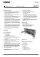
Installation Instructions
Temperature controller
RRV817
Function summary
• The RRV817 temperature controller is designed for
centrally controlling underfloor heating systems in com-
bination with the QAX810 master room unit and
QAW810 zone room units.
• The system is divided into up to 7 zones by way of
on/off control of zone valves.
• One RRV817 in master mode can be used to control up
to five 5 zones, or – with 1 additional RRV817 con-
nected and set to slave mode – the maximum of 7
zones can be centrally controlled.
• The RRV817 in master mode has 1 digital output (DO)
available for switching a local heat source (boiler) and 1
digital input (DI) for remote on/off control from a home
automation system or other remote switching device.
• The default room unit for zone 1 is the QAX810 master
room unit. QAW810 room units are used for additional
zones 2…7.
• The room units acquire and communicate their individ-
ual zone temperatures, and the demand for each zone
is evaluated based on the corresponding zone setpoint.
The zone valve for a corresponding zone will be
opened when there is demand for heat and closed
when there is no demand.
Installation
Place of installation
• Mounting choices:
− Control cabinet
− Control panel
− Wall, ceiling space, cupboard
• Easy access is required for service staff
• The controller should not be freely accessible for the
building occupants.
• Do not install outdoors without using suitable weather
protection.
• Permissible ambient temperature: 0…50 °C.
• Cable strains relief is recommended for all wiring to
avoid disconnection.
The RRV817 temperature controller must be mounted
by an electrician (preferably in an electrical control
panel). Adequate measures must be taken to ensure
degree of protection IP30! Other mounting locations
are possible provided the relevant standards are
observed (including IP30).
As a minimum requirement, the connecting cables
must conform to H05.
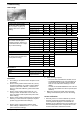
Permissible cable lengths
• For all field devices: Room unit, sensors
− Max. 60 m, A ≥0.5 mm
2
− Max. 100 m, A ≥1.0 mm
2
• Signal cable type
− 2-wire standard installation cable (unshielded)
− Bus topology is free configuration. Ring, star, etc.
− Twisted pair (unshielded) is recomended for en-
hanced immunity to external electromagnetic inter-
ference, e.g. in the vicinity of radio transmitters or
variable speed drives.
• The RRV817 can be mounted in any orientation. En-
sure adequate air circulation to dissipate heat gener-
ated during operation.
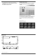
Wall mounting
1. Remove top cover
2. Hold controller against the surface
3. Mark fixing holes on the wall
4. Remove controller and drill the holes
5. Screw controller to the surface
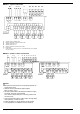
Connections
RRV817 connection terminals
L AC 230 V line
N AC 230 V neutral
TX+ RS-422 Transmit +ve
TX- RS-422 Transmit –ve
RX+ RS-422 Receive +ve
RX- RS-422 Receive –ve
D1 Digital input
M Digital ground
S+ Communication bus +ve
SG Communication bus ground
L… AC 230 V, zone valve power supply
N… AC 230 V neutral
Y… Digital outputs, AC 230 V, 3(1) A
Q… Digital outpus, AC 230 V, 3(1) A