
User Manual

Siemens Building Technologies / HVAC Products 4 319 2788 0 f G2381en 09.03.2004 1/10
4 319 2788 0
G2381en
en
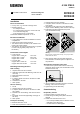
Installation Instructions
District heating and
d.h.w. controller
RVD110
RVD130
Installation
Place of installation
• In a dry room, e.g. the heat exchanger room
• Mounting choices:
- In a compact station
- In a control panel (in the front, on the inner wall,
or on a DIN mounting rail)
- In the sloping front of a control desk
Permissible ambient temperature: 0...50 °C
Electrical installation
• Local regulations for electrical installations must be
complied with
• Cable tension relief must be ensured
• The cables from the controller to the actuators and
pumps carry mains voltage
• The cables to the sensors should not be run parallel
to mains carrying cable (safety class II to
EN 60730!)
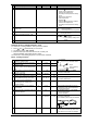
Permissible cable lengths
• For all sensors:
Copper cable 0.6 mm dia. 20 m max.
Copper cable 1.0 mm
2
80 m max.
Copper cable 1.5 mm
2
120 m max.
• For room units:
Copper cable 0.6 mm dia. 37 m max.
Copper cable ≥0.8 mm dia. 75 m max.
Mounting and wiring the base
Wall mounting
1. Separate base from the controller
2. Hold base against the wall. Marking “TOP“ must be
at the top!
3. Mark fixing holes on the wall
4. Drill holes
5. If required, knock out holes on the base for cable
entry glands
6. Screw base to the wall
7. Wire up base
DIN rail mounting
1. Fit rail
2. Separate base from the controller
3. If required, knock out holes on the base for cable
entry glands
4. Fit base to the rail. Marking “TOP“ must be at the
top!
5. If required, secure base (depending on the type of
rail used)
6. Wire up base
Flush panel mounting
• Maximum thickness: 3 mm
• Panel cutout required: 92 × 138 mm
1. Separate base from the controller
2. If required, knock out holes on the base for cable
entry glands
3. Insert base in the panel cutout from behind until
stop is reached. Marking “TOP“ must be at the top!
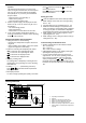
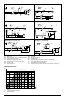
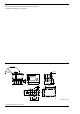
4. Push lateral tongues behind the front panel
(refer to illustration below)
2462Z06
Wrong Correct
Place tongues on both sides correctly – they may not be lo-
cated inside the cutout!
5. Wire up base. Make sure the cable lengths are
such that there is sufficient space to open the con-
trol panel door
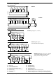
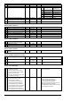
Securing the controller to the base
1. Ensure correct position and location of levers by
turning the fixing screws (refer to illustration on the
lateral wall of the unit)
2522Z13
2. Insert controller in the base until stop is reached.
Marking “TOP“ must be at the top!
3. Tighten fixing screws alternately
Commissioning
Preparatory checks
1. DO NOT switch on power supply yet
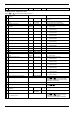
2. Check wiring according to the plant connection
diagram
3. Check each motorized valve: see if
- it is correctly installed (observe direction of flow
indicated on the valve body)
- the manual lever is disengaged