2 510 District Heating Controller for 1 heating circuit and d.h.w. heating RVD120 RVD140 Multifunctional heating controller for use in district heating substations and district heating plants with Modbus communication. Suited for one heating circuit with d.h.w. heating in instantaneous systems or with storage tank. Eight programmed plant types. Operating voltage AC 230 V.
Functions Heating circuit control • Weather-compensated flow temperature control, mixing valve with 3-position actuator • Weather-compensated flow temperature control with room temperature influence, mixing valve with 3-position actuator • Room temperature-compensated flow temperature control, mixing valve with 3position actuator • Demand-dependent control of the common flow D.h.w. heating • D.h.w. heating via heat exchangers in storage tanks • Instantaneous d.h.w.
Product documentation Type of documentation Basic Documentation Operating instructions (languages: de, en, fr, it, da, fi, sv ) Operating instructions (languages: pl, cs, el, ru, bu, ro) Installation instructions (languages: de, en, fr, it, da, fi, sv) Installation instructions (languages: pl, cs, el, ru, bu, ro CE Declaration of Conformity Environmental Declaration Classification number P2510 B2510 Part number – 74 319 0683 0 B2510 74 319 0684 0 G2510 74 319 0681 0 G2510 74 319 0682 0 T2510 E2510
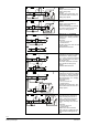
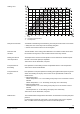
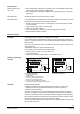
B9 T Plant type no. 2 – RVD120 and RVD140 Heating circuit control with d.h.w. heating (storage tank). RVD140: Circulating pump, refill function, electric immersion heater and solar d.h.w. heating pump optional A6 N1 M1 U2 B1 T M3 T M7 T Y1 M T T T B7 P B71 M T U1 B32 Kx B9 T U2 B1 P M1 T M T Y1 M7 B6 B3 Kx T T B7 Plant type no. 3 – RVD120 and RVD140 Heating circuit control with d.h.w. heating (storage tank).
B9 B71 T N1 A6 M1 U2 B1 P Y5 M M3 T M B3 T Y1 B6 Kx T B7 P M U1 T T B32 Kx A6 B1 B3 B32 B6 B7 B71 B9 H5 Kx M7 Room unit / room sensor Flow sensor (controlled variable) D.h.w. sensor / storage tank sensor 1 Storage tank sensor 2 (only with RVD140) Collector sensor (only with RVD140) Primary return sensor Universal sensor Outside sensor Flow switch (only with RVD140) Multifunctional output K6 or K7 (only with RVD140) Plant type no. 8 – only RVD140 Heating circuit control with d.h.
Generation of flow temperature setpoint • Weather-compensated control: The flow temperature setpoint is controlled in function of the prevailing outside temperature via the heating curve • Weather-compensated control with room temperature influence: The flow temperature setpoint is controlled in function of the prevailing outside temperature and, in addition, in function of the deviation of the actual room temperature from the setpoint • Room temperature-compensated control: The setpoint is controlled in f
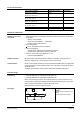
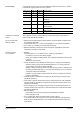
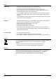
2510D01 Heating curve s TAM TV Slope Composite outside temperature Flow temperature Relay and sensor tests To facilitate commissioning and fault tracing, both relay and sensor tests can be made: • Relay test: each of the relays can be manually energized • Sensor test: all sensor values can be interrogated Pulse lock with actuators The total duration of the closing pulses delivered to an actuator is limited to five times the actuator's running time, in order to extend the life of the relay contacts.
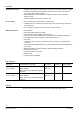
D.h.w. heating In addition to heating circuit control, the RVD120/140 provide control of d.h.w. heating in the following types of plant and d.h.w. systems: Plant type no. RVD120 1 2 3 4 5 6 7 8 RVD140 D.h.w.
Extra functions Remote operation via room units • Room unit QAW50: changeover of operating mode, room temperature setpoint adjustments and room temperature readjustments • Room unit QAW70: overriding the setpoints and the heating program, entry of holiday periods Parameter reset All settings made can be reset to the factory settings. Manual operation In manual operation, the heating can be controlled manually. In that case, d.h.w.
Notes Engineering • • • • Mounting • Suitable mounting locations are compact stations, control panels, control desks or the heating room.
Technical data Power supply Operating voltage Frequency Power consumption (no external load) External supply line protection AC 230 V (+10 / –15 %) 50 Hz RVD120: max. 5.5 VA RVD140: max. 6.5 VA Slow-blow fuse max. 10 A or Circuit breaker max.
Standards, directives and approvals Environmental compatibility Eco design and labeling directives Product standard EN 60730-1 Electromagnetic compatibility (Applications) EU conformity (CE) RCM-conformity (EMC) EAC conformity Product environmental declaration (contains data on RoHS compliance, materials composition, packaging, environmental benefit, disposal) Automatic electrical controls for household and similar use For use in residential, commerce, lightindustrial and industrial environments CE1T2
Connection diagrams Low voltage side RVD120 L Modbus RTU RS485 (EIA-485) AC 230 V * A+ B- B3 N RVD140 L Modbus RTU RS485 (EIA-485) A6 B9 B71 B1 B6 H5 B32 AC 230 V * A+ B- B6 B3 B32 U2 M U1 H5 N2 N * Terminating resistor 150 Ω (0.5 W) for the first and last device on the bus. See Modbus specification for details Mains voltage side RVD120 (Plant types no. 1, 2, 3) 1 actuator and 2 pumps or 1 actuator, 1 pump and 1 changeover valve Q3/Y7 N1 M1 M3 Y7 RVD140 (Plant type no.
Dimensions max. 3 +1 max. 5 +0.8 max. 8 IEC 61554 - 144 × 96 Dimensions in mm Published by: Siemens Switzerland Ltd. Building Technologies Division International Headquarters Theilerstrasse 1a 6300 Zug Switzerland Tel. +41 58-724 24 24 www.siemens.