
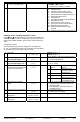
Installation Instructions


Building Technologies 74 319 0681 0 a CE1G2510en 25.08.2009 1/12
74 319 0681 0
G2510
en
Installation Instructions
District heating and d.h.w. controller
RVD120
RVD140
Keep these instructions with the controller!
Installation
Place of installation
• In a dry room, e.g. the heat exchanger room
• Mounting choices:
– In a compact station
– In a control panel (in the front, on the inner wall, or
on a top hat rail)
– In the sloping front of a control desk
• Permissible ambient temperature: 0…50 °C
Electrical installation
• Local regulations for electrical installations must be
complied with
• Only qualified staff may carry out electrical installations
• Cable tension relief must be ensured
• Cable glands made of plastic must be used
• The cables from the controller to the actuators and
pumps carry mains voltage
• The cables to the sensors may not be run parallel to
mains carrying cable (safety class II to EN 60730!)
• If a device is defective or damaged, immediately
disconnect it from power and replace it
Permissible cable lengths
• For all sensors:
Copper cable 0.6 mm dia. 20 m max.
Copper cable 1.0 mm
2
80 m max.
Copper cable 1.5 mm
2
120 m max.
• For room units:
Copper cable 0.25 mm
2
25 m max.
Copper cable from 0.5 mm
2
50 m max.
• For the data bus
Copper cable ≥0.25 mm
2
1000 m max.
(2-wire, twisted pairs, shielded)
For details, refer to the modbus specification
Mounting and wiring the base
Wall mounting
1. Separate base from the controller
2. Hold base against the wall. Marking “TOP“ must be
at the top!
3. Mark fixing holes on the wall
4. Drill holes
5. If required, knock out holes on the base for cable
glands
6. Screw base to the wall
7. Wire up base
Rail mounting
1. Fit top hat rail
2. Separate base from the controller
3. If required, knock out holes on the base for cable
glands
4. Fit base to the rail. Marking “TOP“ must be at the top!
5. If required, secure base (depending on the type of rail
used)
6. Wire up base
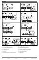
Flush panel mounting
• Maximum thickness: 3 mm
• Panel cutout required: 138 × 92 mm
1. Separate base from the controller
2. If required, knock out holes on the base for cable
glands
3. Insert base in the panel cutout from behind until stop
is reached. Marking “TOP“ must be at the top!
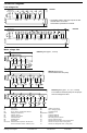
4. Push lateral tongues behind the front panel
(refer to illustration below)
2462Z06
Wrong Correct
Place tongues on both sides correctly – they may not be
located inside the cutout!
5. Wire up base. Make sure the cable lengths are such
that there is sufficient space to open the control panel
door
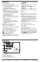
Securing the controller to the base
1. Ensure correct position and location of levers by turn-
ing the fixing screws (refer to illustration on the lateral
wall of the unit)
2540Z04
2. Insert controller in the base until stop is reached.
Marking “TOP“ must be at the top!
3. Tighten fixing screws alternately