
Basic Documentation

If the boiler temperature falls below 5 °C, the burner is always switched on and
keeps running until the boiler temperature exceeds its minimum limit by the amount
of the switching differential.
11.4.4 Protective boiler startup
If the boiler temperature falls below the minimum limit of the boiler temperature
while the burner is running, the temperature differential (minimum limit value minus
actual value) is integrated. From this, a critical locking signal is generated and
forwarded to the connected consumers. This causes the loads to reduce their
setpoints, aimed at consuming less energy. If the critical locking signal exceeds
a defined value, the boiler pump is deactivated as well.
If the boiler temperature returns to a level above the minimum limit, the integral is
reduced, resulting in a reduction of the critical locking signal.
If the integral falls below a defined level, the boiler pump is activated again. The
connected consumers increase their setpoints again.
When the integral reaches the value of zero, protective boiler startup becomes
inactive, in which case the critical locking signal is zero.
If protective boiler startup is active, the boiler temperature controller's display
shows
.
Protective boiler startup cannot be deactivated.
Chapter 17.4.6 "Locking signal gain" provides information on who receives the
boiler temperature controller's critical locking signal and how the consumers re-
spond to it.
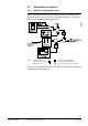
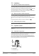
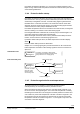
Controller 1
Plant type 3-1
Controller 1 generates a critical locking
signal which deactivates the heating circuit
pump and the d.h.w. charging pump
2524B02e
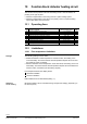
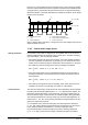
Controller 1
Plant type 3-1
Controller 2
Critical locking signal
LPB
2524B03e
Controller 1 switches
pump M1 off and
shuts the heating
circuit mixing valve
Critical locking signal
Controller 3
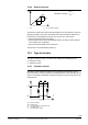
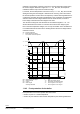
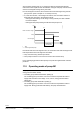
11.4.5 Protection against boiler overtemperatures
To prevent heat from accumulating in the boilers (protection against
overtemperature), the controller provides a protective function.
When the first burner stage is shut down, the controller allows pump M1 to run
for the set overrun time (operating line 174 on the boiler temperature controller),
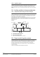
forwarding at the same time a forced signal to all loads (inside the controller and
on the data bus). If the boiler temperature controller is located in segment 0, the
forced signal is sent to all consumers in all segments. By contrast, if the boiler
temperature controller is located in segment 1...14, the signal is only sent to the
consumers in the same segment.
Autonomous unit
Interconnected plant
49/108
Siemens Basic Documentation RVP340, RVP350, RVP351 CE1P2545en
Building Technologies 11 Function block: Boiler 2018-07-27