
User Manual

Siemens Building Technologies Phoenix Application :52 RWD62/52 - 05.2001
HVAC Products RWD62 2
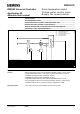
The temperature sensor senses the room conditions and on a rise in temperature
the RWD62 via Y1 analogue output modulates the chilled water valve as
determined by the cooling set point and proportional band (XP) setting.
On a further rise in temperature the RWD62 via the Y2 analogue output
modulates the supply fan via a fan speed controller, as determined by the
proportional band (XP) setting.
Y2 output begins immediately after Y1 reaches maximum output, there is no dead
zone between Y1 and Y2 output.
The limit duct sensor senses the supply air temperature, and maintains the
absolute (actual) maximum and / or minimum supply air temperatures.
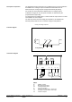
Cooling and cooling sequences
Y1
Min V
Cooling Setpoint
Ouptut
Voltagee
Max V
Cooling
Y2
Max V
Min V
XP
XP
Cooling
Y1
G
Y1
S1
D1
GO
Y..
BM
X1 X2MM
RWD62/3
0
X1
M
M
GO
G
24 V SN
24 V SP
N1
TOOL
PC
Y2
G
M
Y2
BM
G
X2
RWD62
N1 RWD62 controller
X1 Main temperature sensor
X2 Limit temperature sensor
S1 Time clock or switch
Y1 Cooling control valve with 0..10Vdc input
Y2 Fan speed controller with 0..10Vdc input
PC Personal computer
Description of operation
Function diagram
Connection diagram