
User Manual

Siemens Building Technologies Application :68 RWD68/68 - 02.2001
HVAC Products RWD68 2
The temperature sensor senses the room conditions and on a rise in temperature
the RWD68 via Y1 analogue output is compared to other zone controllers . The
maximum call for cooling from other zone controllers is fed to the X2 input of the
final temperature controller and via the maximum priority function of Y1 the
highest call for cooling controls the position of the cooling valve.
The Q1 digital output energises the chilled water pump as determined by the Q1
ON and OFF settings as the chilled water valve opens.
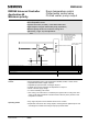
Cooling sequences
Y1
Q1
Load
Output
Voltage
OFF
ON
Setpoint
Min V
Max V
Cooling
XP
Y1
G
Y1
S1
D1
GO
Y..
BM
X1 X2MM
3367A03
X1
M
M
GO
G
24 V SN
24 V SP
N1
TOOL
PC
Q12 Q14
Q11
Q1
CWP
G
0..10Vdc analogue output
from other controller
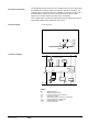
RWD68
N1 RWD68 controller
X1 Main temperature sensor
X2 0..10Vdc input from other controller.
S1 Time clock or switch
Q1 Potential-free relay contacts for on / off control
Y1 Valve actuator with 0..10Vdc input
CWP Chilled water pump contactor
PC Personal computer
Description of operation
Function diagram
Connection diagram