
User Manual
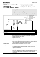

Siemens Building Technologies Application :26 RWD82/26 - 02.2001
HVAC Products RWD82 1
RWD82/26
RWD82 Universal Controller
Application 26
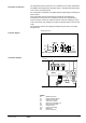
W / S mode selection - digital
Room temperature control
One stage electric heating
Package unit – 1 heat, 1 cool
Control 2 stage digital
Room temperature control
One stage ON / OFF electrical heating
One stage heat – one stage cool - package unit
Winter / Summer selection of heating or cooling operation of Q1 output by X2
Optional day / night set point adjustment .
S1
X1
X2
D1
Q1
Q2
CP
........RWD82.......
M1
RWD32/24
X1
X2
S1
Q1
Q2
PC
HLT
PS
HR
Room temperature sensor
Outside air temperature sensor
Time clock or switch
First stage package unit heat / cool
Second stage electric air heater
Personal computer
High limit thermostat
Pressure switch
Heater relay
X1
Universal analogue input - main sensor
Auxiliary analogue input
Digital input
Digital output
Communication port
P
HLT
PS
T
T
Digital output
HR
X2
T
• Room temperature sensor can be selected as Ni1000, Pt1000, or active sensor.
• Adjustable differential of digital output Q1.
• Adjustable set point of Q1.
• Adjustable differential of digital output Q2.
• Adjustable set point of Q2.
• 24Vac controller supply voltage
• O / A temperature sensor can be selected as Ni1000, Pt1000, or active sensor.(X2)
• Winter / summer selection of heating or cooling mode of the Q1 output as selected by
digital input into auxiliary input X2 sensing outside air temperature.
• Day / night set points can be selected via time clock or switch.
• A high limit manual reset thermostat is mounted downstream of the air electric heater,
and de-energises the heater on excessive duct temperatures. This thermostat has to
be manually reset following detection of overheating. It is often supplied by the
supplier of the electric heater.
• A pressure switch is also specified to detect loss of static pressure in the duct,
indicating loss of fan. This also de-energises the electric heater but it is auto reset and
allows electric heater function following the detection of fan operation.
• These safety units can be connected directly in series with small electric heaters, but
for larger electric heaters they are connected to a heater contactor switching the
electric heater.
Supplemental features
Control
Operating modes
Safety functions