
User Manual

Siemens Building Technologies Application :53 RWD82/53 - 05.2001
HVAC Products RWD82 2
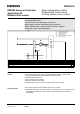
The temperature sensor senses the room conditions and on a rise in temperature
the RWD82 via Q1 digital output energises the chilled water pump.
A further rise in temperature Q2 opens the two position chilled water valve.
In this application the Q1 – ON position should be set to 5 – 10% of the SD
differential setting.
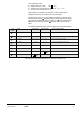
Relative supply air control is maintaining maximum and/or minimum difference
between supply air and room temperature setpoint when the temperature
difference drops below or exceeds the limiter setpoints.
The limiter function overrides the standard control function to maintain the limiter
setpoints.
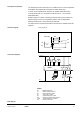
Cooling sequences
Q1
Load
OFF
ON
SD
Cooling Setpoint
C.W. Valve
ON
OFF
Q2
C.W. Pump
G
S1
D1
G0
BM
X1 X2MM
X1
M
G AC 24 V
Q12 Q14
RWD82
Q11
Y1
Q2
Q22 Q24
Q21
Y2
G0
Q1 Q2
N1
TOOL
PC
G
G0
Q1 CWP
M
B
G
X2
RWD82
N1 RWD82 controllers
X1 Main temperature sensor
X2 Limit temperature sensor.
S1 Time clock or switch
Q1 Chilled water pump output
Q2 24Vac two position valve actuator
CWP Chilled water pump contactor
PC Personal computer
Description of operation
Function diagram
Connection diagram
Main Display