
User Manual


Siemens Building Technologies Application :22 RWD82/22 - 05.2001
HVAC Products RWD82 2
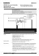
The temperature sensor senses the room conditions and on a fall in temperature
the RWD82 via Q1 digital output energises stage 1 of the electric heater.
On a further fall in temperature, Q2 digital output energises stage 2 of the electric
heater.
The limit duct sensor senses the supply air temperature, and maintains the
absolute (actual) maximum and / or minimum supply air temperatures.
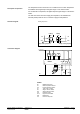
Heating sequences
Q2
Load
Stage 1 Heating Setpoint
OFF
ON
SD SD
2
2
SD
Stage 2 Heating Setpoint
Heating
SD SD
2
2
ON
OFF
SD
Q1
Heating
G
S1
D1
G0
BM
X1 X2MM
X1
M
G AC 24 V
Q12 Q14
RWD82
Q11
Q22 Q24
Q21
Q1 Q2
N1
TOOL
PC
G
G0
Q1
Q2
PS
HLT
HR
L
L
N
N
BM
G
X2
RWD82
N1 RWD82 controllers
X1 Main temperature sensor
X2 Limit temperature sensor
S1 Time clock or switch
Q1 Stage 1 electric heater
Q2 Stage 2 electric heater
PS Pressure switch
HLT High limit thermostat
HR Heater relay
PC Personal computer
Description of operation
Function diagram
Connection diagram