SEZ50MB RWD Primary Controls Modbus Interface Basic Documentation CB1P3099en_01 27.10.
Siemens Switzerland Ltd. Building Technologies Group International Headquarters Gubelstrasse 22 CH-6301 Zug Tel. +41 41-724 24 24 Fax +41 41-724 35 22 www.siemens.com/sbt © 2009 Siemens Switzerland Ltd. Subject to change 2 / 26 Siemens Building Technologies RWD Primary Controls Modbus Interface CB1P3099en_01 27.10.
Table of Contents 1 About This Document ................................................................................. 4 1.1 Before Starting............................................................................................... 4 1.2 Additional Documents.................................................................................... 4 1.3 Abbreviations & Terminologies ...................................................................... 5 1.4 Important Notes ........................
RWD Products 1 About This Document 1.
1.3 NA R-only W-only R-W Hex Modbus 1.4 Abbreviations & Terminologies Not Available Read Only Write Only Read & Write Hexadecimal Value Modbus is a serial communication protocol published by Modicon. It has become a standard communications protocol in industry. Important Notes This symbol draws your attention to special safety notes and warnings. If such notes are not observed, personal injury and / or considerable damage to property would occur.
2 SEZ50MB Overview Product Overview The SEZ50MB enables remote monitoring on RWD devices in the same Modbus network. Please referred to SEZ50MB datasheet CB1N3099.
RS232 Interface A 1.5 meters long RS232 cable is provided together with SEZ50MB and the RS232 cable is one-to-one type (the same pin numbers are connected at both ends of this cable). The DB9 male socket of the RS232 cable will be connected to RWD device while the female plug will be connected to SEZ50MB. The table below lists the pin numbers and their corresponding functions of DB9 female plugs of RS232 interface connected to SEZ50MB: Pin No.
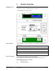
3 Commissioning SEZ50MB Before connecting any RWD products to SEZ50MB, the RWD device must be configured to one of its available applications manually or via RWD SW configuration tool (Please refer to RWD documentation for more information). Configuring RWD Manually The RWD device connected with SEZ50MB must be configured to a selected application first. Various applications for each RWD can be selected via key buttons with the help of the LCD display on the RWD.
Modbus Connection For best performance, the single BUS topology is highly recommended.
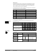
4 Modbus Function Codes Modbus Operation The valid Function Codes are as follows: Function Data Code (Hex) Length 0x01 RWD Parameter Functions Addressable 1 Read R/W Flag (Coil) 0xxxx 0x05 1 Write R/W Flag (Coil) e.g. 00001, 00003 0x02 1 Read R-only Flag (Discrete Input) 0x03 2 Read R/W Register (Holding Register) 4xxxx 0x10 2 Write R/W Register e.g. 40109, 40111 0x04 2 Read R-only Register (Input Register) Ranges 1xxxx e.g. 10004 3xxxx e.g.
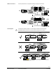
Function Code 0x03 à Read RWD68 parameter (ADDR = 40117, 40118) called “SP3day” with Modbus ADDR = 0116, 0117: SEZ50MB Function Device Code Modbus Address Data Length CRC16 Check 00 90 Address Send F7 03 00 74 02 SEZ50MB Function Byte Status Device Code Count (IEEE 754 format) 03 04 41 E0 00 00 87 CRC16 Check Address Respond F7 79 F6 (SP3 day setpoint 28 °C) Function Code 0x04 à Read RWD68 parameter (ADDR = 30055, 30056) called “RWDAPP” with Modbus ADDR = 0054, 0055: SEZ50
Exception Codes Whenever an unexpected message is received or an error is encountered by SEZ50MB, the SEZ50MB would return a RESPOND for such errors. Modbus communicaton frame contains an error field for exception codes, which can be used by network application to determine what appropriated action will be taken.
Function Code 0x04 à (Error Message) Read RWD68 parameter (ADDR = 30055, 30056) called “RWDAPP” with Modbus ADDR = 0054, 0055: SEZ50MB Function Code Modbus Address Data Length 04 00 CRC16 Check Device Address Send F7 00 36 00 or 01 85 53 ↑ WRONG INFO SEZ50MB Function Device Code Exception Code CRC16 Check 14 A3 Address Respond Function Code 0x05 à (Error Message) F7 84 3D Write RWD32S parameter (ADDR = 00001) called “bFrostEnable” with Modbus ADDR = 0000: SEZ50MB Function Code Mod
Notes: • The SEZ50MB only support Modbus commands for either READ or WRITE of one parameter each time. If access to consecutive parameters is required, users should issue multiple commands manually or via any Modbus SW tool; • Each command string may vary depending on function code used, some function codes may take longer time to be processed by SEZ50MB.
Parameters RWD RWD Parameter Parameters Data Format Detailed Descriptions & Data Interpretation 0xFF00 For RWD32S only, represent 1 0: Frost Protect Disabled 0x0000 1: Frost Protect Enabled Addresses 00001 * bFrostEnable represent 0 00002 * bGRADEnable 0xFF00 For RWD32S only, represent 1 0: GRAD Disable 0x0000 1: GRAD Enable represent 0 00003 * B3_Display 0xFF00 For RWD32S only, represent 1 0: Disable the display of B3 sensor 0x0000 1: Enable the display of B3 sensor represent
RWD RWD Parameter Parameters Data Format Detailed Descriptions & Data Interpretation Addresses 30007 Y1_output IEEE754 Analog Output of Y1 30009 Y2_output IEEE754 Analog Output fo Y2 30011 TempUnit IEEE754 For RWD32S Temp Unit 0: Celsius 1: Fahrenheit 30013 SensorType IEEE754 For RWD32S Sensor Type 0: NI 1000 1: PI 1000 30015 D1_func IEEE754 For RWD34/44/45 only, Function Setting for Input D1 0: ON/OFF 1: Day/Night 2: Alarm 3: Filter Alarm 30017 UNIT IEEE754 For RWD32/62/68/82 &
RWD RWD Parameter Parameters Data Format Detailed Descriptions & Data Interpretation Addresses 3: Stage3 30029 RWDType IEEE754 RWD Type 0: RWD62 1: RWD34 2: RWD32S 3: RWD68 4: RWD32/82 5: NA 6: RWD45 7: RWD44 30031 X1_H IEEE754 High Range for X1 (Sensor) Input 30033 X1_L IEEE754 Low Range for X1 (Sensor) Input 30035 X2_H IEEE754 High Range for X2 (Sensor) Input 30037 X2_L IEEE754 Low Range for X2 (Sensor) Input 30039 X3_H IEEE754 High Range for X3 (Sensor) Input 30041 X3_L IE
RWD RWD Parameter Parameters Data Format Detailed Descriptions & Data Interpretation Addresses 1: The cost has passed 9999 Bit 7: Reserved and fixed to 0 30055 RWDAPP IEEE754 RWD Application Number 30057 SensorStat Refer to each Status of Various Sensors bit for For RWD32/62/68/82, explanation (only Bits 0 to 3 are for users) Bit 0: X1 error status 0: No error, 1: Error Bit 1: X2 error status 0: No error 1: Error Bit 2: X1 range status 0: Within range 1: Out of range Bit 3: X2 range status
RWD RWD Parameter Parameters Data Format Detailed Descriptions & Data Interpretation Addresses 40003 ALTWIN IEEE754 Winter ChangeOver Set Point 40005 Eco_xp IEEE754 P Band in Economy Cool Mode 40007 LIMMAX_Cas IEEE754 Maximum of Absolute Limiter. (Used in RWD32/62/68/82, application no = 15, 25, 35, 45, etc.) 40009 LIMMIN_Cas IEEE754 Minimum of Absolute Limiter. (Used in RWD32/62/68/82, application no = 15, 25, 35, 45, etc.
RWD RWD Parameter Parameters Data Format Detailed Descriptions & Data Interpretation IEEE754 Set Point of Cooling for ind Y for Day Addresses 40091 * SP_ind_C_day (Used in RWD45 application no = 70 to 99) 40093 * SP_ind_C_night IEEE754 40095 * SP_ind_H IEEE754 40097 * SP_ind_H_day IEEE754 Set Point of Cooling for ind Y for Night (Used in RWD45 application no = 70 to 99) Set Point of Heating for ind Y (Used in RWD45 application no = 70 to 99) Set Point of Heating for ind Y for Day (Used in
RWD RWD Parameter Parameters Data Format Detailed Descriptions & Data Interpretation Addresses 40157 * XDZ_H3 IEEE754 Offset for H3 40159 XP_ind IEEE754 P Band for Ind Y 40161 XP1 IEEE754 P Band for Heating 1 40163 XP1_cas IEEE754 P Band for Cascade Heating 1 40165 XP2 IEEE754 P Band for Heating 2 40167 XP3_cas IEEE754 P Band for Cascade Cooling 1 40169 XP_3P IEEE754 P Band for 3P (Used in RWD82, application no = 30 to 39 and 70 to 79) 40171 Y1_max IEEE754 Max Output for
RWD RWD Parameter Parameters Data Format Detailed Descriptions & Data Interpretation Addresses 30 to 130: 30 ℃ to 130 ℃ If the TempUnit is F, 0: OFF 86 to 266: 86 ℉ to 266 ℉ 40195 * T_Abs IEEE754 The absolute charging temperature If the TempUnit is C, 30 to 90 representing 30 ℃ to 90 ℃ If the TempUnit is F, 86 to 194 representing 86 ℉ to 194 ℉ 40197 * D_SP IEEE754 Delta Set Point If the TempUnit = C, 0 to 40 representing 0 ℃ to 40 ℃ If the TempUnit =F, 0 to 80 representing 0 ℉ to 80 ℉ 40199 L
6 Appendix A:Standard IEEE-754 Format According to IEEE Standard 754-1985, IEEE754 specifies binary representations for floating point numbers. 6.1.1 General Description A real-valued number is represented in a floating-point format as: (-1)Sign × Significant ×2Exponent • • • Sign is 0 for positive values, 1 for negative values. Significant is a real number, composed as integer fraction, while integer=1. Exponent is an integer value. 6.1.
7 Appendix B: Generating A CRC16 Check Sum The following CRC Generation Function is based on docuement called: Modbus over serial line specification and implementation guide V1.02 from www.Modbus.
Low-Order Byte Table /* Table of CRC values for low–order byte */ static char auchCRCLo[] = { 0x00, 0xC0, 0xC1, 0x01, 0xC3, 0x03, 0xC7, 0x05, 0xC5, 0xC4, 0x04, 0xCC, 0x0C, 0x0D, 0xCD, 0x0F, 0xCB, 0x0B, 0xC9, 0x09, 0x08, 0xC8, 0xD8, 0x18, 0x19, 0xD9, 0xDE, 0xDF, 0x1F, 0xDD, 0x1D, 0x1C, 0xDC, 0x14, 0xD4, 0xD5, 0xD2, 0x12, 0x13, 0xD3, 0x11, 0xD1, 0xD0, 0x10, 0xF0, 0x30, 0x32, 0x36, 0xF6, 0xF7, 0x37, 0xF5, 0x35, 0x34, 0xF4, 0x3C, 0x3E, 0xFE, 0xFA, 0x3A, 0x3B, 0xFB, 0x39, 0xF9, 0xF8, 0x38, 0x2B, 0x2A, 0xEA, 0xEE
8 Trouble Shooting Hints 1. What does it mean when I receive “02” exception code? [Reason] It’s often caused by wrong Modbus ID setting. [Resolve] Check Modbus ID setting in third party software and make sure it’s the same as ID setting of DIP switch. 2. What does it mean when I receive “03” exception code? [Reason] It’s often caused by write operation attempting to write an out-of-range value into RWD. [Resolve] Check the value written to RWD. 3.