3 372 PolyCool™ Superheat Controller RWR462.10/ALG For chillers, air conditioning units, etc. • Standalone electronic superheat controller RWR462.10/ALG for use with any type of dry expansion evaporator in refrigeration plants. • The MOP (Maximum Operating Pressure) function and the monitoring of sensors and minimum superheat are integrated. • The controller can be included in the chiller's safety circuit. • Optionally, control of the cooling capacity can be configured. • It operates on AC / DC 24 V.
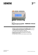
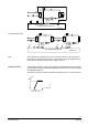
Use The PolyCool™ superheat controller with its associated components ensures optimum operation of the refrigeration unit. EIV 1-4 EN D1 AL Q14 X Y1 p t PO TOH KP X3 Y1 X1 X2 Superheat Control RWR462.10 Field of use The controller ensures optimum filling of the evaporator under all load conditions, resulting in low energy consumption. Various monitoring functions enhance operating safety and extend the plant’s life.
Peripheral devices The PolyCool™ superheat controller uses two types of sensors and one valve made by Siemens HVAC Products. Siemens HVAC Products Field devices Cable Temperature Sensor Pressure sensor Refrigerant valve Type QAZ21.682/101 Measuring range -50…80° C - QBE9103-P10U* - QBE9103-P30U* - QBE9103-P60U* -1…9 bar -1…29 bar -1…59 bar - QBE2004-P10U -1…9 bar - QBE2004-P25U -1…24 bar - QBE2004-P60U -1…59 bar -MVL661..-../ MVS661.25-..
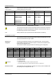
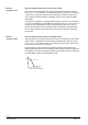
Selection of application For the default: Pure superheat control It is possible to configure the following three different applications. EIV 1-4 EN D1 X AL Q14 p t PO TOH Y1 KP X3 Y1 X1 X2 Superheat Control RWR462.10 External capacity control EIV 1-4 p AL EN D1 X Y1 Q14 X3 Y1 t PO TOH 0...10V / 4...20 mA KP Synco, Saphir and other third-party controller X4 X1 X2 External Capacity Control RWR462.
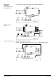
EIV TM p EN X AL D1 Q14 Y1 1-4 t PO TOH Ni1000 KP X1 X2 X3 Y1 X5 Internal Capacity Control (2) RWR462.10 Two superheat circuits EIV EIV 1-4 EN D1 AL Q14 X Y1 X3 Y1 p t PO TOH p KP EN X1 X2 D2 AL Q24 Two Superheat Circuits Y2 Y2 1-4 t PO TOH KP X4 X5 RWR462.10 Note This controller can be applied to two pure superheat control circuits, but only one EIV feedback can be input (terminal X3).
External capacity control External capacity control (only for one single circuit) The capacity of the refrigeration unit drops as the superheat increases. Using a DC 0...10 V / 4…20 mA signal, the setpoint of superheat control can be increased via input X4. The signal is calculated and delivered by an external controller (i.e. Synco, Saphir and other third-party controller), based on the measured medium temperature.
Standard functions Enable In general, the control and monitoring functions are enabled by an operational status signal received from the plant. Digital input D1 / D2 When feeding an AC / DC 24 V signal (i.e. operational status signal from the compressor) to the digital input D1 (D2 for circuit 2), the control of the evaporator and the safety functions for the compressor will be activated.
Medium temperature TM • External capacity control DC 0...10 V / 4...20 mA signal from an external controller (Synco, Saphir and other third-party controller) based on the measured medium temperature. A measured value of -0.5 V or 10.5 V ( 3.5 or 20.
Mechanical design Casing The RWR462.10/ALG is a compact controller conforming to DIN 43 880 Gr 1, housed in a closed plastic casing. Mounting choices The superheat controller can be mounted in the control panel in one of the following ways: • • • • In a standard control panel conforming to DIN 43 880 Wall mounting on top hat rails which are already fitted (EN 60715-TH 35-7.5) Wall mounting with two fixing screws Flush panel mounting with the help of the ARG462.
Operating buttons + - To operate the controller, use the operating buttons on the controller front. The operating buttons provide the following functions: Use the button to enable changes or confirm a change. • Use the +/- buttons to change flashing data, or select the information screen. • • Press the to exit out of the current level and back to the previous one.
Configuration mode [CONF] Following the initial power up, the controller automatically enters the configuration mode. In this mode, the type of refrigerant is selected and the unit of temperature °C or °F and pressure Bar or Psi determined. Notes Optionally, control of the cooling capacity can be configured. To reconfigure the controller, refer to "Selection of operation mode" above.
Parameter mode [PARA] Adjustment of all setpoints and parameters, such as proportional band, integral action time for the operation safety controls, superheat, capacity controller, and the MOP function. The setpoint of the MOP function must be adjusted as specified by the supplier of the compressor or as demanded by the application.
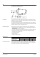
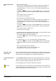
Example Liquid cooler (shell-and-tube heat exchanger) Parameter code ΔT XP ΔT TN MOP XP old 30 K 65 s 20 k MOP TN 40 s [%] new 30 K * 1,25 = 38 K 65 s 50 K / 20K = 2,5 > 0,75 → 50 K / 0,75 = 67 K or higher 40 s Valve Opening Degree (VO) Control Mode VO Time VT Icing Simulation mode [SIMU] Parameter list Important VD [S] Capacity control is accomplished by increasing the superheat. For this reason, a reduction in capacity is always associated with a drop in the evaporation temperature.
Mounting and Installation notes For mounting and electrical installation, the following notes should be observed. Controller A Mounting on DIN rail No additional parts are required. B Wall mounting With four ellipse screws for holes with diameter of 4 mm x 6 mm C Flush panel mounting With HVAC Products ARG462.10 mounting kit Mounting Instruction M 3351.1 Electrical installation The wiring can be made with standard cables.
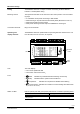
Wiring must be made in compliance with the following connection diagram. 3372A02 Connection diagram X2 X1 G (+) I (-) K1 Please do not G G 0 PE connect M with GND! X5 B M B M K2 D1 M D2 AC/DC 24 V X4 X1 GND X 2 X3 GND X4 X 5 GND Digital Inputs Digital Output AC 24...230 V 5 V 24V DC Universal Input PolyCool Superheat RWR462.
Connection diagram Pressure sensor with DC 0…10 V signal (X1) G0 AC / DC 24 V The following diagram shows example for the wiring of pressure sensor QBE2004 (DC 0…10 V signal) with 3-wire connection (analogue input X1). X1 G U G G0 PE M X1 GND X2 X3 GND X4 X5 GND 5V 24V DC Connection diagram Active temperature sensors (X4) The following diagrams show examples for the wiring of active temperature sensors with 3-wire and 2-wire connections (analogue input X4).
Configuration of DIP Switches Configuration of DIP Switches for analogue inputs (X…) The default factory settings of DIP switches at the rear top of the controller are presented as follows. Bit 1 of J2 is used for factory calibration. To wire the terminals with different types of sensors, configure the DIP Switches as follows.
Selection of refrigerant R22 R170 * R402A R408A R422D R449A R600a * Important When starting up the controller for the first time, the configuration mode appears. First, the correct type of refrigerant and the units must be selected.
Fault status signals Should faults or malfunctions on the controller, valve or sensors occur, the alarm icon will flash and the LCD displays ERR or FAIL in place of the corresponding parameter.
Technical data Operating voltage Safety extra low voltage (SELV) to Frequency AC 24 V 20 % (DC 24 V 10 %) EN 60 730-1 50 Hz / 60 Hz Power consumption RWR462.10/ALG approx. 10 VA (with full configuration) Interrogation rate Cycle time Y1 Cycle time Y1 and Y2 together 0.5 s 0.5 s Display (LCD) Actual values and setpoints Resolution Analog outputs (DC 0...10 V) Digital switching outputs 4 digits 0.1 2 digits, resolution 0.
Signal 0…10 V Range Under- and over- range Resolution Accuracy of RWR462.10/ALG Max. current drawn Internal resistance Ri DC 0…10 V -1.4...11.4 V 10 mV 0.078 V 0.98 mA > 10 k Signal 4…20 mA Range Under- and over- range Resolution Accuracy of RWR462.10/ALG Max. current drawn Internal resistance Ri DC 4…20 mA -3...24 mA 0.02 mA 0.3 mA 24 mA 240 Temperature signal Range Under- and over- range Resolution Accuracy of RWR462.10/ALG Measuring voltage Measuring current -50...80 °C -60...110 °C 0.
Relay outputs Q14, Q24 Weight (excl. Packing) Switching capacity of relay contact Q14, Q24 Alternating current AC 24...230 V, 3 A res., 2 A ind. Direct current max. DC 30 V, max. 5 A Min. contact rating At mains voltage At low voltage Max. starting current AC 230 V / 5 mA DC 24 V / 10 mA 7.5 A (1 s) External fuse on input side max. 10 A Min. Load Initial contact resistance Max. Switching Rate 100 mA at DC 5 V 100 M at 1 A, 6 VDC 300 ops./min. (no load) 20 ops./min.
Dimensions 23 / 24 Siemens Smart Infrastrucutre Superheat Controller CE1N3372en_02 2022-02-16
Index Analog inputs X1…X5 ................... 20 Analog outputs Y1, Y2 ................... 21 Auxiliary functions ............................ 2 Casing .............................................. 9 Checking the peripheral devices ... 18 Commissioning notes .................... 16 Config. and parameter settings ..... 17 Configurable functions ..................... 3 Configuration mode [CONF] .......... 11 Configuration of DIP Switches ....... 17 Connection diagram ...................... 15 Digital input .