
Data Sheet for Product


7 / 24
Siemens Superheat Controller CE1N3372en_02
Smart Infrastrucutre 2022-02-16
Standard functions
In general, the control and monitoring functions are enabled by an operational sta-
tus signal received from the plant.
When feeding an AC / DC 24 V signal (i.e. operational status signal from the com-
pressor) to the digital input D1 (D2 for circuit 2), the control of the evaporator and
the safety functions for the compressor will be activated.
To ensure the reliability of the refrigeration plant and to prolong the life of the com-
pressor, the following protective functions have been integrated:
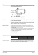
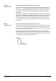
• Minimum limitation of superheat
To protect the compressor from shocks caused by liquid refrigerant, the valve
will be closed in modulating mode when the minimum superheat falls below the
selected parameter value (MI) i.e. 2 K. (3.6 °F).
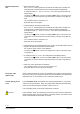
• MOP function [MOP]
Limitation of the maximum evaporation pressure is another protective function
provided for the compressor. It operates in PI mode and overrides the normal
control function to maintain the maximum evaporation temperature.
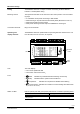
When power is supplied to the controller, relay Q14 (Q24 for circuit 2) will be ener-
gized. The following actions protect automatic control operation against faults at
the universal inputs X_.
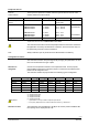
• Measurement of pressure P0
A measured value of 0 V or 10 V ( 4 mA or 20 mA) produces the following
effects:
− The alarm icon flashes, and the LCD displays ERR in place of the actual value
of superheat t, and the respective range limit indicator, low (LO) or high (HI), will
flash
− The controller's output Y1 (Y2 for circuit 2) switches to 0 V
− Relay Q14 (Q24 for circuit 2) will be de-energized *
* When returning to the normal operational values, relay Q14 (Q24) will automatically be energized
again.
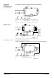
• Measurement of suction gas temperature TOH
For any short-circuit or open-circuit detected:
− The alarm icon flashes, and the LCD displays FAIL in place of the actual value
of superheat t
• A measured value of TL or 70 C will produce the following effects:
− The alarm icon flashes, and the LCD displays ERR in place of the actual value
of superheat t, and the respective range limit indicator, low (LO) or high (HI), will
flash
• When any of the alarms above is detected:
− The controller's output Y1 (Y2 for circuit 2) switches to 0 V
− Relay Q14 (Q24 for circuit 2) will be de-energized
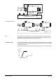
Enable
Digital input D1 / D2
Protective functions for
the compressor
Operating safety
Evaporation
pressure P0
Suction gas
temperature TOH