
Data Sheet for Product


8 / 24
Siemens Superheat Controller CE1N3372en_02
Smart Infrastrucutre 2022-02-16
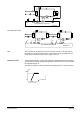
• External capacity control
DC 0...10 V / 4...20 mA signal from an external controller (Synco, Saphir and
other third-party controller) based on the measured medium temperature.
A measured value of -0.5 V or 10.5 V ( 3.5 or 20.5 mA) produces the fol-
lowing effects:
− The alarm icon flashes, and the LCD displays ERR in place of the actual value
of superheat t, and the respective range limit indicator, low (LO) or high (HI), will
flash
− The controller's output Y1 switches to 0 V
− Relay Q14 will be de-energized
• Internal capacity control with active sensor
DC 0...10 V / 4...20 mA signal from an external controller (Synco, Saphir and
other third-party controller) based on the measured medium temperature.
A measured value of -0.5 V or 10.5 V ( 3.5 or 20.5 mA) produces the fol-
lowing effects:
− The alarm icon flashes, and the LCD displays ERR in place of the actual value
of superheat t, and the respective range limit indicator, low (LO) or high (HI), will
flash
− The controller's output Y1 switches to 0 V.
− Relay Q14 will be de-energized
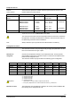
• Internal capacity control with passive sensor (or two circuits with passive sensor)
• Signal from a passive temperature sensor Ni1000.
For any short-circuit or open-circuit detected:
− The alarm icon flashes, and the LCD displays FAIL in place of the actual value
of superheat t
• A measured value of TL or 80C will produce the following effects:
− The alarm icon flashes, and the LCD displays ERR in place of the actual value
of superheat t, with the respective range limit indicator, low (LO) or high (HI), will
flash
• When any of the alarms above is detected:
− The controller's output Y1 (Y2 for circuit 2) switches to 0 V
− Relay Q14 (Q24 for circuit 2) will be de-energized
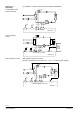
Relay contact Q14 (Q24 for circuit 2) is controlled by the safety functions. Depend-
ing on the circuitry, this changeover contact can be used either for actuating a sep-
arate alarm horn or for integration in the compressor's safety circuit.
In the simulation mode, the required valve opening (default value = 0 %) can be
entered on the user interface. This is very helpful when filling the plant with refrig-
erant, for short-time emergency operation, service work, etc.
In this operating mode, the minimum superheat is monitored.
In the simulation mode, the supervisory functions are active only if the operational
status signal D1 (D2 for circuit 2) is present. For safety reasons, the normal control
mode is automatically resumed after 15 minutes.
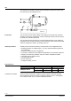
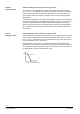
Medium temperature
TM
Relay Q14 / Q24
(Alarm relay)
Forced opening of the
valve
Important