
User`s manual

Semiconductor Group 9-2
Power Saving Modes
C515
9.2 Power Saving Mode Control Register
The functions of the power saving modes are controlled by bits which are located in the special
function register PCON. The bits PDE, PDS and IDLE, IDLS located in SFR PCON select the power
down mode or the idle mode, respectively. If the power down mode and the idle mode are set at the
same time, power down takes precedence. Furthermore, register PCON contains two general
purpose flags. For example, the flag bits GF0 and GF1 can be used to give an indication if an
interrupt occurred during normal operation or during an idle. For this, an instruction that activates
idle can also set one or both flag bits. When idle is terminated by an interrupt, the interrupt service
routine can examine the flag bits.
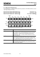
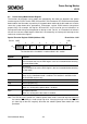
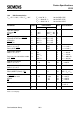
Special Function Register PCON (Address 87
H)
Reset Value : 00
H
Note: The PDS bit, which controls the software power down mode is forced to logic low whenever
the external PE/SWD pin is held at logic high level. Changing the logic level of the PE/SWD
pin from high to low will irregularly terminate the software power down mode and is not
permitted.
Symbol Function
PDS Power down start bit
The instruction that sets the PDS flag bit is the last instruction before entering
the power down mode
IDLS Idle start bit
The instruction that sets the IDLS flag bit is the last instruction before entering
the idle mode.
SD Slow down mode bit
When set, the slow down mode is enabled. This function is available in the
C515-LM/1RM versions only.
GF1 General purpose flag
GF0 General purpose flag
PDE Power down enable bit
When set, starting of the power down is enabled
IDLE Idle mode enable bit
When set, starting of the idle mode is enabled
MSB
LSB
87
H
PCON
SMOD PDS IDLS SD GF1 GF0 PDE IDLE
76543210
Bit No.
The function of the shaded bit is not described in this section.