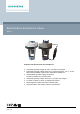
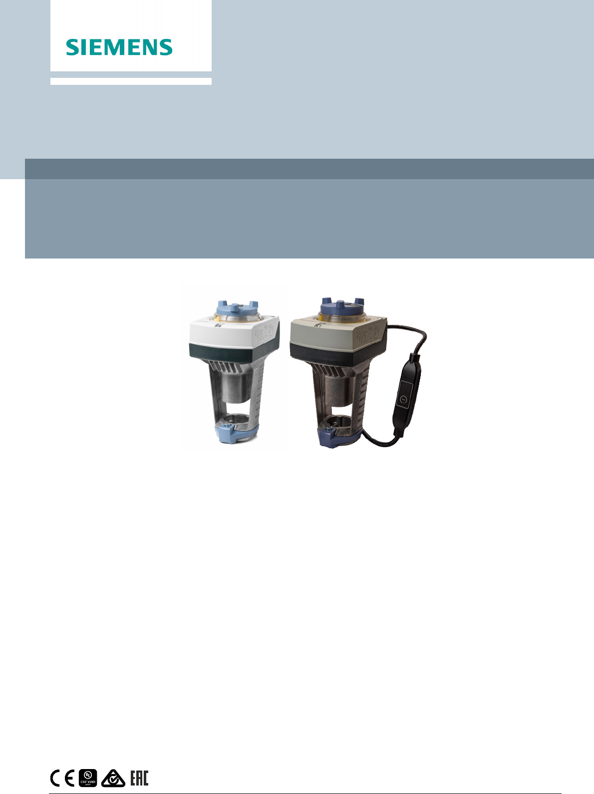
ACVATIX™ Electromotoric actuators for valves SAV..P.. Actuators with 40 mm stroke and 1100 N force ● ● ● ● ● ● ● CE1N4510en 2020-11-26 SAV31P00 Operating voltage AC 230 V, 3-position control signal SAV61P00 Operating voltage AC/DC 24 V, positioning signal 0...10V, 4...
Use Electromotoric actuators to operate Siemens combi valves for type series VPF43.. and VPF53.. with 40 mm stroke, as control valves on ventilation, air conditioning, district heating and refrigeration plants. Functions Function Description 3-position control A 3-position signal controls the actuator via connection terminals Y1 or Y2. The desired position is transmitted to the valve. Modulating control The modulating positioning signal provides stepless motor control.
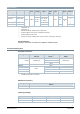
Type summary Type Item No. Stroke Positionin Operatin g force g voltage SAV31P00 1) S55150-A121 SAV61P00 2) S55150-A119 Positioning signal AC 230 V Spring Positionin LED return g time time 3-position Manual adjuster Auxiliary functions 3) - DC ...10 V SAV61P00/MO 2) S55150-A144 SAV81P00 2) S55150-A120 40 mm 1100 N AC 24 V DC 4...20 mA DC 24 V - 0...
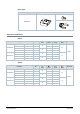
Spare parts Product number / Stock number Housing cover Screw (valve stem coupling) U-bracket 8000060843 Equipment combinations VPF43.. Valve type DN H100 [mm] Standard flow High flow rate VPF43.100F70 S55266-V106 100 VPF43.125F110 S55266-V108 125 VPF43.150F160 S55266-V110 150 VPF43.200F210 S55266-V148 200 VPF43.100F90 S55266-V107 100 VPF43.125F135 S55266-V109 125 VPF43.150F200 S55266-V111 150 VPF43.200F280 S55266-V149 200 40 43 40 43 Min.
Product documentation Title Contents Document ID Actuators SAX.., SAY.., SAV.., SAL.. for valves Basic documentation: CE1P4040en Detailed information on stroke actuators including Modbus types Stroke actuators for valves with 15/20/40 mm stroke and rotary actuators for butterfly valves Electromotoric actuators for valves SA.., Modbus RTU Data sheet: Mounting instructions G..161../MO and S..
SAV61P00 Up to 10 actuators can drive in parallel on a controller output with a rating of 1 mA. Modulating actuators have an input impedance of 100 kΩ. SAV61P00/MO The Modbus converter is designed for analog control at 0...10 V. Keep the analog signal setting on the actuator as is (switch 1 to OFF); adjustment not permitted. ASZ7.5 Actuators with a DC 0...9.8 V feedback signal are recommended for the combination SIMATIC S5/S7 and position feedback. Signal peaks in potentiometer ASZ7.
Operation Direction of control action On valves where the stem retracts to the close position, "direct acting" means that the actuator’s stem is extended when positioning signal Y = 0 V or Z = 0 Ω. Direct acting Y, Z Positioning signal V Volume flow Positioning signal Y DC 0...10 V, 4...20 mA Positioning signal Z 0...1000 Ω Control action: Direct acting Maintenance The actuators are maintenance-free.
Technical data Power Operating voltage SAV31P00 AC 230 V ±15% SAV61P00.. AC 24 V ± 20 % / DC 24 V +20 % / -15 % (SELV / PELV) SAV81P00 Frequency 45...65 Hz External supply line fusing (EU) ● Non-renewable fuse 6...10 A slow ● Circuit break max. 13 A, tripping characteristic B, C, D to EN 60898 ● Power source with current limitation of max. 10 A Power consumption at 50 Hz SAV31P00 SAV61P00 SAV61P/MO 6.5 VA / 4 W Stem retracts/extends SAV81P00 Typical inrush current 1) 9.5 VA / 4.5 W 10.
Communication SAV61P../MO Communication protocol Modbus RTU RS-485, not galvanically isolated Number of nodes Max. 32 Address range 1...248 / 255 Factory setting Transmission formats 255 1-8-E-1 / 1-8-O-1 / 1-8-N-1 / 1-8-N-2 Factory setting 1-8-E-1 Factory setting Auto Baud rates (kbaud) Auto / 9.6 / 19.2 / 38.4 / 57.6 / 76.8 / 115.
Environmental conditions Operation IEC 60721-3-3 Climatic conditions Class 3K5 Mounting location Indoors (weather-protected) Temperature, general -5...55 °C Humidity (non-condensing) 5...95 % r.h. Transportation 4) IEC 60721-3-2 Climatic conditions Class 2K3 Temperature -25...70 °C Humidity < 95% r.h. Storage IEC 60721-3-1 Climatic conditions Class 1K3 Temperature -15...55 °C Humidity 5...95 % r.h. Max.
Accessories 6) Auxiliary switch ASC10.51 Switching capacity External fusing of supply line US installation, UL & cUL AC 24…230 V, 6 (2) A, potential free ● Non-renewable fuse 6...10 A slow ● Circuit break max. 13 A, tripping characteristic B, C, D to EN 60898 ● Power source with current limitation of max.
SAV61P.. Accessories B and / or A SAV61P00 1 x ASC10.51 1 x ASC10.51 SAV61P00/MO SAV81P00 Accessories B and / or A 1 x ASC10.51 1 x ASC10.51 or 1 x ASZ7.5/..
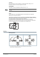
Connection terminals SAV31P00 AC 230 V 3-position System neutral (SN) Positioning signal (actuator’s stem extends) Positioning signal (actuator’s stem retracts) SAV61P00 AC / DC 24 V D 0...10 V 4...20 mA 0...1000 System neutral (SN) System potential (SP) Positioning signal for DC 0...10 V / 4...
Connection diagrams SAV31P00 A Actuator L Phase N Neutral N1 Controller Y1, Y2 Positioning signals SAV61P00 A Actuator F2 Frost protection thermostat: terminals: 1 – 2 frost hazard / sensor is interrupted (thermostat closes with frost) 1 – 3 normal operation 14 Siemens Smart Infrastructure F3 Thermal reset limit thermostat F4 Frost protection monitor with 0…1000 Ω signal output, does NOT support QAF21.. or QAQ61..
SAV61P00/MO A Actuator N1 Controller G System potential AC/DC 24 V G0 System zero REF Reference line (Modbus RTU) + Bus + (Modbus RTU) - Bus - (Modbus RTU) SAV81P00 Siemens Smart Infrastructure A Actuator N1 Controller SN System zero SP System potential Y1, Y2 Positioning signals 15 CE1N4510en 2020-11-26
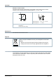
Dimensions Actuator Type A B C C1 C2 D E [mm] SAV..P.. SAV61P00/MO With ASK39.1 1) 16 Siemens Smart Infrastructure 1) 265 124 150 68 82 290 154 300 200 100 [kg] 80 100 100 - 200 1.920 2.070 2.
External Modbus converter Dimensions in mm Type X SAV61P00/MO 1) Siemens Smart Infrastructure [mm] [kg] 250 0.15 1) Included in total weight.
Revision numbers Type Valid from rev. no. SAV31P00 ..B SAV61P00 ..C SAV61P00/MO ..B SAV81P00 ..C Issued by Siemens Switzerland Ltd Smart Infrastructure Global Headquarters Theilerstrasse 1a CH-6300 Zug Tel. +41 58 724 2424 www.siemens.com/buildingtechnologies 18 Siemens Smart Infrastructure Document ID CE1N4510en Edition 2020-11-26 © Siemens Switzerland Ltd, 2011 Technical specifications and availability subject to change without notice.